Electric power construction cable temporary connection twining device

A temporary connection and power construction technology, applied in the direction of connection, line/collector components, circuits, etc., can solve problems such as loosening, splashing and falling off of insulation skin, and achieve the effect of reducing travel and improving dredging efficiency

Active Publication Date: 2018-03-23
HUNAN HENGGUANG TECH
View PDF6 Cites 2 Cited by
  • Summary
  • Abstract
  • Description
  • Claims
  • Application Information

AI Technical Summary

Problems solved by technology

[0002] At present, cable winding connection is required in electric power construction sites. Line distribution connection from high-voltage cables and lap connection on low-voltage lines must be connected through guided winding. During the connection process, first Cut off the insulating layer, and then wind the metal wire. When cutting the insulating layer, the insulating sheath splashes everywhere and needs to be cleaned later. Due to the material of the metal core, it is difficult to wind tightly between the two strands of metal wire during winding. , It is easy to fall off during use, resulting in poor contact for power supply, especially for some temporarily lapped circuits. Traditionally, two strands of metal wires are clamped by pliers, and then wound by hand. However, the whole power supply will be wound When winding occurs, it affects the layout of the line. Some existing connecting joints are only used to protect the metal wires after they are connected. It is not detachable, and it is not suitable for the temporary construction of the line network, and it is not convenient for later disassembly. The existing connecting terminals that are easy to be disassembled all adopt a plug-in structure. When encountering natural factors such as wind, they will fall off, resulting in line interruption. , and the diameter range of the connecting line of the connector is limited, different line connections need to prepare different connectors
[0003] Publication number CN103326167A discloses an electrical connector assembly and a cable connector, the electrical connector assembly includes a first connector, which has an insulating body and a number of conductive terminals arranged on the insulating body; the insulating body has A base and a plugging part, each conductive terminal has a butt joint, a fixing part, an elastic part and a welding part; the electrical connector combination also includes a base and an outer frame, and the outer frame is surrounded by the base A receiving space is formed to accommodate the base of the insulating body, and the outer frame is provided with an opening for the first connector to go out, wherein there is a floating gap between the opening and the first connector; The base of the insulating body is provided with an abutting portion with a first curved surface, and the bottom wall of the base is correspondingly provided with a supporting portion with a second curved surface, wherein the supporting portion and the abutting portion are movably matched to make the The first connector is floatingly arranged on the base, and the invention connects the lines in the form of plugging, which is easy to separate during use, and the result is complicated and not suitable for temporary line overlapping

Method used


Image

  • Electric power construction cable temporary connection twining device

Examples


Embodiment Construction

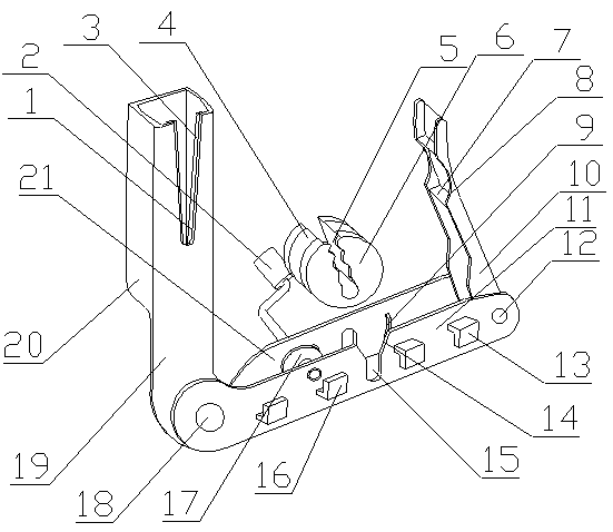
[0021] The temporary connection winding device for electric power construction cables of the present invention is realized as follows: When in use, the two power cords that need to be connected are put into the stripping tank (1), so that the power cord reserves a certain length in the slag storage In the box (20), slide the power cord along the skin cutter (3) to cut the insulation layer on the outer surface of the power cord, and then pull it to the outside of the slag storage box (20) to make the insulation fall off in the slag storage box (20). ), and then pass the two wires through the waist-shaped holes on the auxiliary vertical plate (21), so that the two wires are guided through the insulating layer and stuck in the waist-shaped holes, and the connecting part of the metal wire passes through the winding rotor (6) The card slots (5) are arranged in sequence between the wave-shaped baffles (7) on the card slots (5), and a certain length is reserved to pass through the open...


PUM


Abstract

The invention relates to a power construction cable temporary connection twining device, and discloses a device for clamping and fixing a connection end of a metal wire and twining and connecting themetal wire by rotation. The device is characterized in that one end of a connecting plate is vertically placed at the bottom of a slag storage box, a peeling groove is formed in the slag storage box,the slag storage box is an open container, the peeling groove is an open groove, cutters are respectively placed on two side walls of the peeling groove, the cutting edge of the cutters is of a zigzagstructure, a main vertical plate is vertically placed on one side edge of a base plate, the other end of the connecting plate is placed on one end of the main vertical plate by a rotating shaft, an open groove is formed in the central portion of the main vertical plate, main fixing and clamping plates are placed on the main vertical plate and located on one side of the open groove, auxiliary fixing and clamping plates are placed on the main vertical plate and located on the other side of the open groove, the main fixing and clamping plates and the auxiliary fixing and clamping plates are L-shaped plates, the opening directions of the main fixing and clamping plates and the auxiliary fixing and clamping plates are opposite, and an auxiliary vertical plate is vertically placed on the otherside of the base plate and is parallel to the main vertical plate.

Description

Technical field [0001] The invention provides a wire winding device for temporary connection of electric power construction cables, which relates to a device for temporarily winding connection points of lines when electric power cables are wired, and belongs to the field of electric power construction. In particular, it relates to a device that clamps and fixes the connecting end of a metal wire, and rotates the metal wire to wind the connection. Background technique [0002] At present, the winding connection of cables is needed in the electric power construction site. The line distribution connection from the high-voltage cable and the overlap connection on the low-voltage line must be connected by guided winding. During the connection process, first Cut off the insulating layer, and then wind the metal wire. When cutting the insulating layer, the insulating skin splashes around and needs subsequent cleaning. Due to the material of the metal core, it is difficult to wind tightl...

Claims


Application Information

Patent Timeline
Patent Type & Authority Applications(China)
IPC IPC(8): H01R43/033
Inventor 不公告发明人
Owner HUNAN HENGGUANG TECH
Why Eureka
Try Eureka