
Safety locking structure with anti-theft function for electrical equipment

An electrical equipment and safety locking technology, applied in electrical components, fastening devices of wing fans, building structures, etc., can solve problems such as damage to precision components, safety accidents, threats to personal safety, etc., and achieve convenient opening and protection. The effect of personal safety and simple device structure

Active Publication Date: 2019-05-21
江西省一互电气有限公司
View PDF4 Cites 0 Cited by
  • Summary
  • Abstract
  • Description
  • Claims
  • Application Information

AI Technical Summary

Problems solved by technology

[0005] Aiming at the deficiencies of the prior art, the present invention provides a safety locking structure with an anti-theft function for electrical equipment, which solves the problem that the existing electrical equipment does not have a fast and safe locking structure when it is in use, so that others can lock it when it is opened. It may cause damage to internal precision components, or even a safety accident, threatening personal safety

Method used

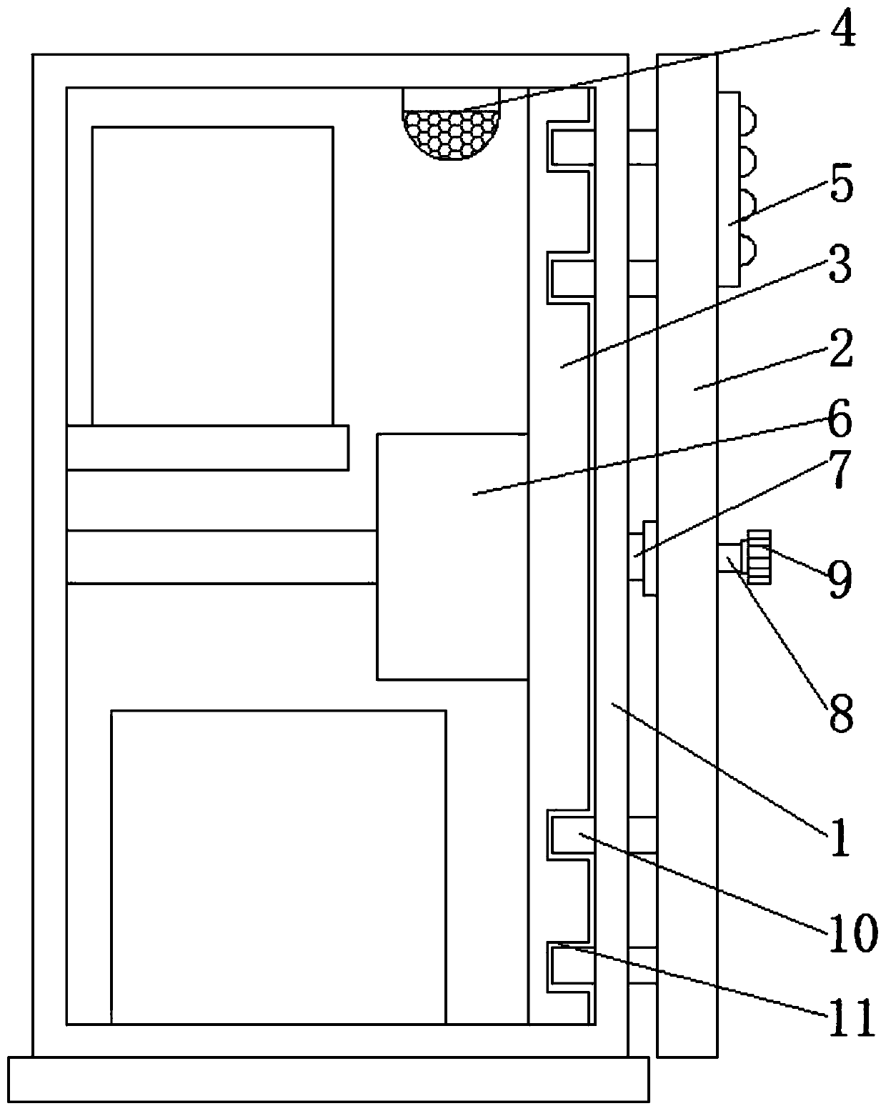

Image

  • Safety locking structure with anti-theft function for electrical equipment
  • Safety locking structure with anti-theft function for electrical equipment
  • Safety locking structure with anti-theft function for electrical equipment

Examples


Embodiment Construction

[0025] The following will clearly and completely describe the technical solutions in the embodiments of the present invention with reference to the accompanying drawings in the embodiments of the present invention. Obviously, the described embodiments are only some, not all, embodiments of the present invention. Based on the embodiments of the present invention, all other embodiments obtained by persons of ordinary skill in the art without making creative efforts belong to the protection scope of the present invention.

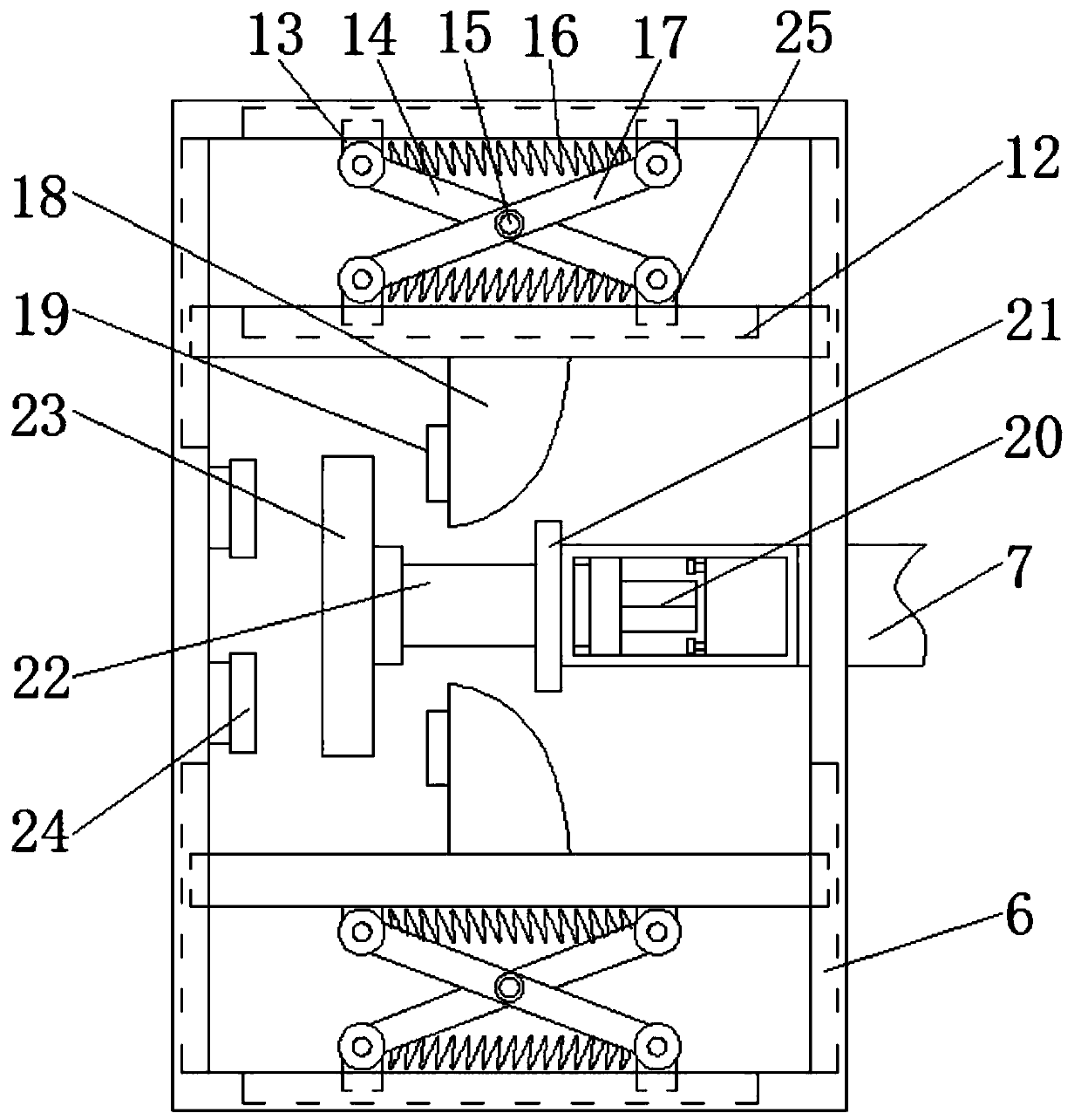
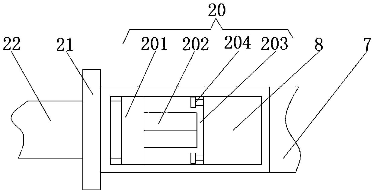
[0026] see Figure 1-4, the embodiment of the present invention provides a technical solution: a safety locking structure with anti-theft function for electrical equipment, including an electrical box 1, one side of the electrical box 1 is rotatably connected with a box door 2, and the left side of the inner wall of the electrical box 1 The locking box 6 is fixedly connected through the support plate, and one side of the box door 2 is fixedly connected with an...


PUM


Abstract

The invention discloses a safety locking structure with the anti-theft function for electrical equipment. The safety locking structure comprises an electrical box; a box door is connected to one sideof the electrical box in a rotating manner; and a locking box is fixedly connected to the left side of the inner wall of the electrical box by a support plate. An extruding plate that is fixedly connected to one side of the box door penetrates the locking box and extends to the inside of the locking box; and a push plate is fixedly connected to a connection device by a connection plate. Two movingplates are connected between the two sides of the inner wall of the locking box in a sliding manner; and first sliding blocks are connected to one side of the inner wall of the locking box in a sliding manner and a second sliding block is connected to one side of each moving plate in a sliding manner. The safety locking structure relates to the technical field of electrical equipment. With the safety locking structure, clamping is carried out effectively and thus locking is done conveniently, so that time wasting is reduced; when a non-professional operator opens the structure, alarming is carried timely for prompting, so that safety is improved substantially.

Description

technical field [0001] The invention relates to the technical field of electrical equipment, in particular to a safety locking structure with an anti-theft function for electrical equipment. Background technique [0002] Electrical equipment is a general term for generators, transformers, power lines, circuit breakers and other equipment in the power system. The important role played by electricity in our life and production cannot be ignored. It brings us great convenience and becomes our The production of vital energy in life. The most critical factor for the normal operation and transmission of electricity in the power plant is the electrical equipment. In order to prevent damage to the insulation of the electrical equipment, the voltage to the ground of the metal casing of the electrical equipment is limited within a safe value to avoid electric shock and harm the human body. Ground the part of the electrical equipment that is equivalent to a conductor that leaks out. ...

Claims


Application Information

Patent Timeline
Patent Type & Authority Patents(China)
IPC IPC(8): H02B1/46E05C19/00
CPCE05C19/00H02B1/46
Inventor 刘新林
Owner 江西省一互电气有限公司
Learn More