
Charger output current control system

A technology of output current and control system, which is applied in current collectors, battery circuit devices, electric vehicles, etc., and can solve problems such as terminal overheating and excessive temperature difference

Inactive Publication Date: 2018-03-23
XUZHOU YIER ENVIRONMENTAL PROTECTION TECH CO LTD
View PDF0 Cites 0 Cited by
  • Summary
  • Abstract
  • Description
  • Claims
  • Application Information

AI Technical Summary

Problems solved by technology

[0005] In view of the problems existing in the above-mentioned prior art, the present invention provides a charger output current control system, which solves the technical problem of local overheating of the terminal due to the excessive temperature difference between the two chargers, and achieves the goal of maintaining the two chargers The technical effect of similar temperature

Method used


Image

  • Charger output current control system

Examples


Embodiment Construction

[0010] The present invention will be further described below in conjunction with accompanying drawing.

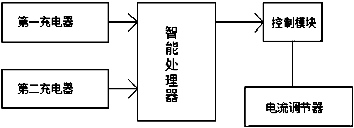
[0011] Such as figure 1 As shown, a charger output current control system includes a first charger, a second charger, an intelligent processor, and a control module. The first charger and the second charger are connected to the input terminal of the controller, and the control module Connect the output of the intelligent processor.

[0012] Further, the control module is a current regulator.

[0013] When the first charger and the second charger charge the battery, acquire the temperature of the first charger and the temperature of the second charger; calculate the difference between the temperature of the first charger and the temperature of the second charger; When the absolute value of the difference is greater than the predetermined difference threshold, the output current of the charger with high temperature among the first charger and the second charger is adjusted ...


PUM


Abstract

The invention discloses a charger output current control system. The charger output current control system comprises a first charger, a second charger, an intelligent processor and a control module; the first charger and the second charger are connected with the input end of a controller; and the control module is connected with the output end of the intelligent processor. By virtue of the chargeroutput current control system, the technical problem of overhigh partial temperature of a terminal caused by overhigh temperature difference between the two chargers can be solved, and a technical effect of maintaining similar temperatures of the two chargers can be realized.

Description

technical field [0001] The invention relates to a charger output current control system. Background technique [0002] In the early days, when people used high current charging, they usually used one charger to charge, which caused the charger to heat up severely and affect the charging efficiency. In the later period, people used double chargers to charge to alleviate the severe heating on one charger. [0003] In the related art, in the constant current charging stage, the output currents of the main charger and the auxiliary charger are each half of the total output current. And compared with the auxiliary charger, the main charger not only charges the battery, but also supplies power to the terminal load. [0004] Because the main charger needs to supply additional power to the terminal load, the temperature difference between the two chargers will be too large, and the positions of the main charger and the auxiliary charger on the circuit board are different, which wi...

Claims


Application Information

Patent Timeline
Patent Type & Authority Applications(China)
IPC IPC(8): H02J7/00
CPCH02J7/0071
Inventor 贾文彬王振亚刘伟宇孟庆楠
Owner XUZHOU YIER ENVIRONMENTAL PROTECTION TECH CO LTD
Learn More