Double-sided anti-fog mouth mirror
An anti-fog, double-sided technology, applied in oral mirrors, endoscopes, medical science, etc., can solve the problems of mouth mirror fogging and affecting normal observation, and achieve the effect of preventing rapid fogging
- Summary
- Abstract
- Description
- Claims
- Application Information
AI Technical Summary
Problems solved by technology
Method used
Image
Examples
Embodiment 1
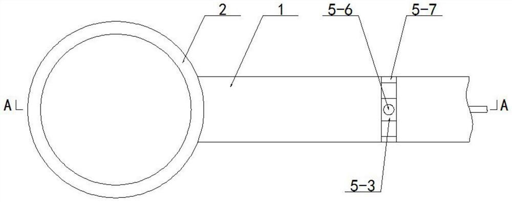
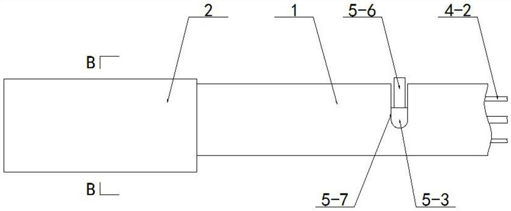
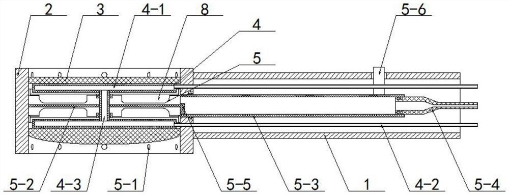
[0039] like figure 1 , 2 , 3, this embodiment includes a handle 1, a mirror frame 2, and a mirror body 3, wherein the mirror frame 2 is welded on the handle 1, and the mirror bodies 3 are two, and they are stacked and arranged in the mirror frame 2. The side edge is sealed and fixed on the inner side wall of the frame 2 by sealant, and it also contains:
[0040] The heating and anti-fogging piece 4, the heating and anti-fogging piece 4 is arranged in the handle 1, and after its end passes through the handle 1, it is arranged between the mirror bodies 3 on the front and rear sides;
[0041] A blow drying part 5, the blow drying part 5 is arranged in the mirror frame 2;
[0042] With the above design scheme, in use, the mirror body 3 is heated by heating the anti-fog element 4, so that the temperature of the mirror body 3 is raised to 40°C, thereby preventing the mirror body 3 from condensing on the surface of the mirror body 3 during the working process. Fog, when there is w...
Embodiment 2
[0044] like image 3 , 4 As shown, on the basis of the above-mentioned embodiment 1, the heating and anti-fog component 4 includes:
[0045] There are two heat-conducting boxes 4-1, and two of the heat-conducting boxes 4-1 are respectively welded on the walls on the opposite side of the mirror body 3 on the front and rear sides;
[0046] There are two guide tubes 4-2, which are respectively penetrated and fixed on the side plates of the heat conduction boxes 4-1 on the front and rear sides, and the other end of the guide tubes 4-2 is pierced. After passing through the side plate of the frame 2, it is placed on the handle 1;
[0047] A connecting pipe 4-3, the connecting pipe 4-3 is arranged between the heat conducting boxes 4-1 on the front and rear sides, and the front and rear ends of the connecting pipe 4-3 respectively pass through the heat conducting boxes 4 fixed on the front and rear sides. On the board of -1, the heat conduction boxes 4-1 on the front and rear sides...
Embodiment 3
[0050] like Figure 5 As shown, on the basis of the above-mentioned Embodiment 2, the heat conduction box 4-1 is provided with a deflector 6, and the deflector 6 is spirally wound around the port side of the connecting pipe 4-3 to guide the The side edge of the flow plate 6 is glued and fixed on the inner side wall of the heat conduction box 4-1;
[0051] With the above design scheme, after the warm water enters the heat conduction box 4-1, the water flow is guided by the deflector 6, and then the water flow travels in a spiral shape, and then the water flow covers and contacts the inner wall of the heat conduction box 4-1.
PUM
 Abstract
Description
Claims
Application Information
 - R&D
- Intellectual Property
- Life Sciences
- Materials
- Tech Scout
- Unparalleled Data Quality
- Higher Quality Content
- 60% Fewer Hallucinations
Browse by: Latest US Patents, China's latest patents, Technical Efficacy Thesaurus, Application Domain, Technology Topic, Popular Technical Reports.
© 2025 PatSnap. All rights reserved.Legal|Privacy policy|Modern Slavery Act Transparency Statement|Sitemap|About US| Contact US: help@patsnap.com


