A method for direct power control of a combined power supply device

A power supply device and power control technology, which is applied in the field of combined power supply devices, can solve the problems of transformer steady-state magnetic flux phase difference, high switching requirements, closing surge overcurrent, etc., and achieve the effect of improving adaptability

Inactive Publication Date: 2019-08-20
SOUTHWEST JIAOTONG UNIV
View PDF5 Cites 0 Cited by
  • Summary
  • Abstract
  • Description
  • Claims
  • Application Information

AI Technical Summary

Problems solved by technology

When the ground is over-voltage and phase-separated, the electric locomotive (EMU) performs voltage conversion in the neutral section. It is a load-disconnecting phase-splitting switch, which will produce a cut-off overvoltage, which has high requirements for the switch; at the same time, it is full-load and closes another phase-splitting switch. Switch, there is a traction transformer on the locomotive, because the two phases are different, the steady-state magnetic flux of the transformer has a phase difference, and the closing surge overcurrent will be caused by dynamic magnetic flux saturation when closing
For locomotives that rotate the motor and draw power from the traction transformer, it will also cause overcurrent in the auxiliary system when the switch is closed

Method used


Image

  • A method for direct power control of a combined power supply device
  • A method for direct power control of a combined power supply device
  • A method for direct power control of a combined power supply device

Examples


Embodiment Construction

[0041] The present invention will be further described in detail below in conjunction with the accompanying drawings and specific embodiments.

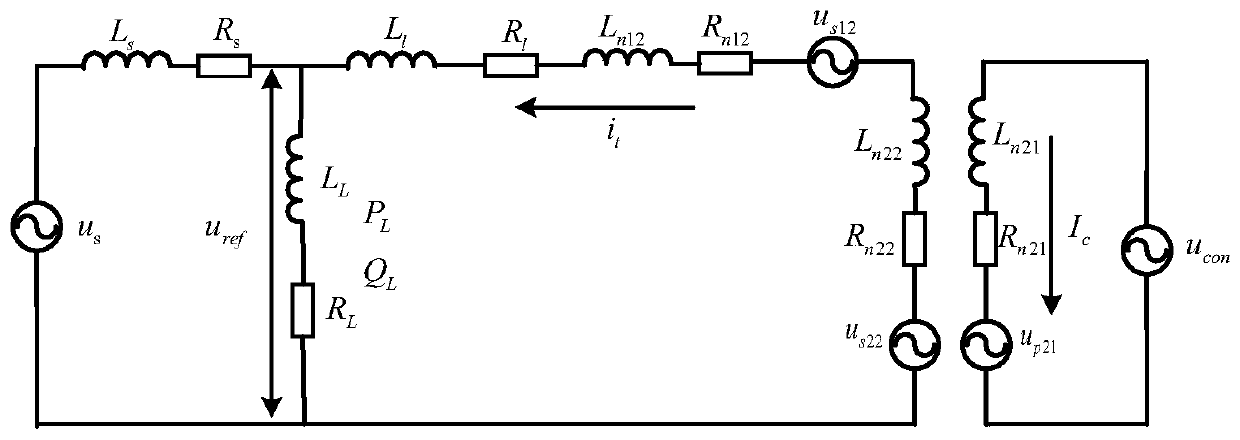
[0042] image 3 Equivalent circuit diagram for parallel connection of combined power supply device and traction power supply arm, u in the figure s12 for the transformer T 1 Secondary winding n 12 The induced voltage, R n12 for the winding n 12 The equivalent resistance, L n12 for the winding n 12 The equivalent inductance of u s22 for the transformer T 2 Secondary winding n 22 The induced voltage, R n22 for the winding n 22 The equivalent resistance, L n22 for the winding n 22 The equivalent inductance of u p21 for the transformer T 2 Primary winding n 21 The induced voltage, R n21 for the winding n 21 The equivalent resistance, L n21 for the winding n 21 The equivalent inductance, R l is the equivalent resistance of the output line of the combined power supply device, L l is the equivalent inductance of the outp...


PUM


Abstract

The invention discloses a method for direct power control of a combined power supply device, which aims at using a transformer T 1 , Transformer T 2 In the combined power supply device that supplies power to the neutral section with the converter CON, the transformer T 1 Winding voltage u 12 The d-axis component and q-axis component of the transformer T 2 Secondary winding voltage drop and transformer T 2 The voltage drop of the primary winding is processed accordingly, and the d-axis voltage component and q-axis voltage component required by the converter CON are obtained by direct power control, and then modulated to obtain the required output voltage of the converter, so as to realize the output voltage of the entire power supply device Adjustment to achieve the purpose of controlling the output power of the combined power supply device. The invention realizes the controllable adjustment of the output power of the combined power supply device.

Description

technical field [0001] The invention relates to the fields of AC-DC-AC electric locomotives (EMUs), ground over-current phase separation devices for AC-DC electric locomotives, combined power supply devices for virtual in-phase power supply, etc., in particular to a direct power control method for combined power supply devices. Background technique [0002] There are many methods for electric locomotive (EMU) over-voltage phase separation. In the early days, the speed of trains was relatively slow, and manual over-power phase separation was usually used. There was a phase-separation sign in the phase-separation area to instruct the driver to operate over-power phase separation. Before reaching the neutral section, the driver first reduces the traction level to 0, disconnects the auxiliary system, and then disconnects the main circuit breaker on the primary side of the traction transformer, so that the locomotive passes through the neutral section without electricity. After t...

Claims


Application Information

Patent Timeline
Patent Type & Authority Patents(China)
IPC IPC(8): H02M5/42
Inventor 熊成林雷海杨皓黄路杨丰波宋智威冯晓云
Owner SOUTHWEST JIAOTONG UNIV
Why Eureka
Try Eureka