Current switching control method based on cascaded multilevel over-electric phase break system

A cascading multi-level, over-current phase-splitting technology, which is applied to power lines, transportation and packaging, and vehicle components, can solve problems such as auxiliary system overcurrent, voltage phase inconsistency, closing surge overcurrent, etc., to achieve Improving adaptability and avoiding the effects of transient processes

Inactive Publication Date: 2017-02-08
SOUTHWEST JIAOTONG UNIV
View PDF7 Cites 15 Cited by
  • Summary
  • Abstract
  • Description
  • Claims
  • Application Information

AI Technical Summary

Problems solved by technology

It can be seen that the improved solution still cannot completely solve the shortcomings of the traditional ground over-current phase-splitting device, and the complexity and cost of the system are increased due to the need to use step-down transformers
[0006] To sum up, there are the following problems in the ground overvoltage phase separation device of the prior art: 1) Since it is a full-load breaking switch in the whole process, the requirements for the switch are relatively high; Opening the split-phase switch will produce cut-off overvoltage; 3) When the voltage is switched in the neutral section, the voltage phase before and after the switch is inconsistent, and there will be a difference in the steady-state magnetic flux of the traction transformer on the locomotive. Saturation causes closing surge overcurrent
For locomotives that rotate the motor and draw power from the traction transformer, it will also cause overcurrent in the auxiliary system when the switch is closed

Method used


Image

  • Current switching control method based on cascaded multilevel over-electric phase break system
  • Current switching control method based on cascaded multilevel over-electric phase break system
  • Current switching control method based on cascaded multilevel over-electric phase break system

Examples


Embodiment Construction

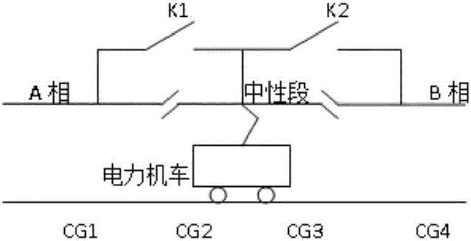
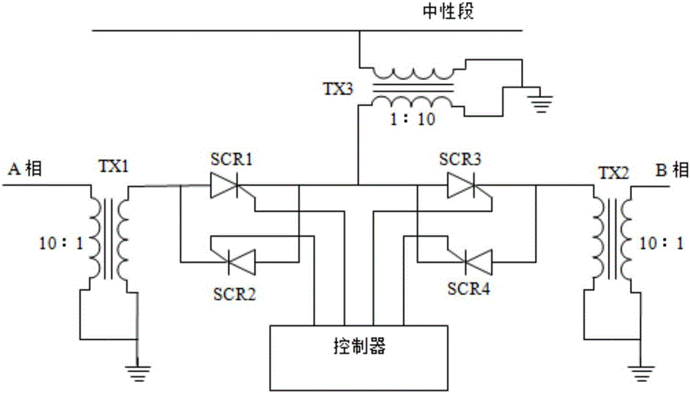
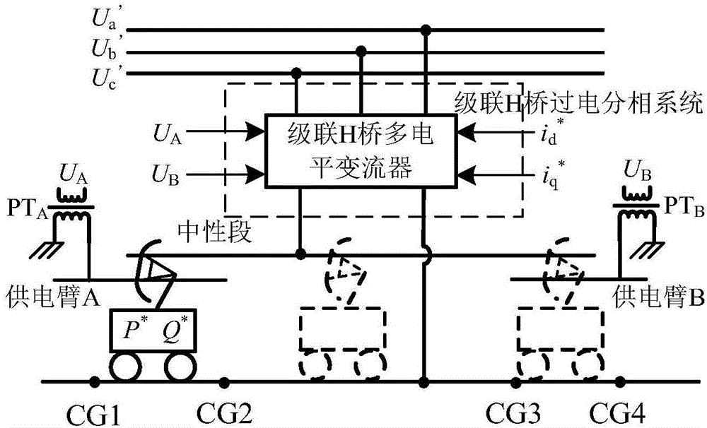
[0026] The present invention will be further described in detail below in conjunction with the accompanying drawings and specific embodiments. The system is equipped with locomotive position sensors CG1, CG2, CG3, and CG4 for determining the position of the locomotive, and contactors for measuring the phase of the catenary voltage are set between the catenary power supply arm A, the catenary power supply arm B and the overvoltage phase separation device. The grid voltage phase detection module PTA and the catenary voltage phase detection module PTB are equipped with a real-time receiving device for the load current of the electric locomotive. A system composed of cascaded multi-level ground overcurrent phase-splitting devices such as image 3 As shown, the current switching control schematic diagram of the present invention is as follows Figure 4 , Figure 5 As shown, its specific implementation process is as follows:

[0027] 1. When the train is running from CG1 to CG4 ...


PUM


Abstract

The invention discloses a current switching control method based on a cascaded multilevel over-electric phase break system. A current transformer of the cascaded multilevel over-electric phase break system is controlled to output current; when a pantograph of a train is in contact with a power supply arm of a traction power supply network and a neutral section at the same time, controllable switching of load current, required by the train, between the power supply arm of the traction network and the neutral section is realized, so that no impact current is generated when the pantograph is separated from or connected to the power supply arm of the traction network or the neutral section, and the adverse effect on a vehicle network in a transient process is avoided. According to the current switching control method, when an electric locomotive or a motor train unit passes through the cascaded multilevel over-electric phase break system, no impact is generated during load current switching of the train, the problems of arc discharge and overvoltage of interceptive current are solved, and the train can flexibly pass through an electrical split phase.

Description

technical field [0001] The invention relates to the field of electric phase separation using a traditional single-phase power frequency traction power supply system and the like, and specifically relates to a current switching control method based on a cascaded multi-level ground overvoltage phase separation system. Background technique [0002] There are many methods for electric locomotive (EMU) over-voltage phase separation. In the early days, the speed of trains was relatively slow, and manual over-power phase separation was usually used. There was a phase-separation sign in the phase-separation area to instruct the driver to operate over-power phase separation. Before reaching the neutral section, the driver first reduces the traction level to 0, disconnects the auxiliary system, and then disconnects the main circuit breaker on the primary side of the traction transformer, so that the locomotive passes through the neutral section without electricity. After the locomotiv...

Claims


Application Information

Patent Timeline
Patent Type & Authority Applications(China)
IPC IPC(8): B60M3/04
CPCB60M3/04
Inventor 熊成林吴瑕杰刁飞雷海葛兴来宋文胜冯晓云
Owner SOUTHWEST JIAOTONG UNIV
Why Eureka
Try Eureka