Power control method based on cascaded multilevel ground overvoltage phase splitting system

A cascaded multi-level, over-power phase separation technology, applied in power lines, transportation and packaging, vehicle parts, etc., can solve the problems of production cut-off over-voltage, inconsistent voltage phase, closing surge over-current and other problems, reaching The effect of improving adaptability and avoiding transient processes

Inactive Publication Date: 2016-05-04
SOUTHWEST JIAOTONG UNIV
View PDF6 Cites 23 Cited by
  • Summary
  • Abstract
  • Description
  • Claims
  • Application Information

AI Technical Summary

Problems solved by technology

It can be seen that the improved solution still cannot completely solve the shortcomings of the traditional ground over-current phase-splitting device, and the complexity and cost of the system are increased due to the need to use step-down transformers
[0006] In summary, the existing ground over-current phase separation device has the following problems: 1) Since it is a full-load breaking switch in the whole process, the requirements for the switch are relatively high; 2) When the neutral section voltage is converted, it is a If the split-phase switch is disconnected, a cut-off overvoltage will be generated; 3) When the voltage is switched in the neutral section, the voltage phase before and after the switch is inconsistent, and there will be a difference in the steady-state magnetic flux of the traction transformer on the locomotive. Saturation causes closing surge overcurrent
However, it has not involved the controllable switching between the power supply arm and the neutral section of the train required by the train

Method used


Image

  • Power control method based on cascaded multilevel ground overvoltage phase splitting system
  • Power control method based on cascaded multilevel ground overvoltage phase splitting system
  • Power control method based on cascaded multilevel ground overvoltage phase splitting system

Examples


Embodiment Construction

[0024] The present invention will be further described below in conjunction with drawings and embodiments.

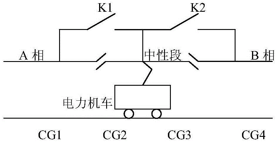
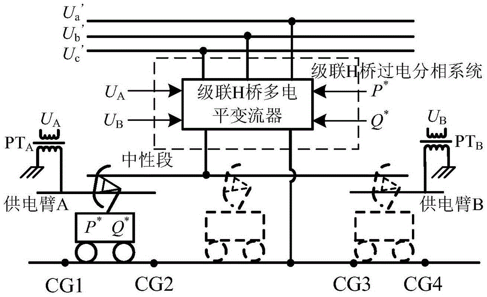
[0025] The locomotive position sensors CG1, CG2, CG3, CG4 for determining the position of the locomotive and the catenary voltage for measuring the catenary voltage phase are respectively connected between the phases A and B of the catenary power supply arm and the overcurrent phase splitting device Phase detection module PT A and PT BIn a system composed of an electric locomotive power real-time receiving device and a cascaded multi-level ground over-current phase-splitting device, such as image 3 As shown in the embodiment, the power control schematic diagram disclosed by the present invention is as follows Figure 4 As shown, its specific implementation is as follows:

[0026] 1. When the train runs from CG1 to CG4,

[0027] 1) When the train does not reach CG1, the reference active power and reference reactive power of the converter in the given corresponding s...


PUM


Abstract

The invention discloses a power control method based on a cascaded multilevel ground overvoltage phase splitting system. The converter part of the cascaded multilevel ground overvoltage phase splitting system is controlled, and by controlling the amplitude and phase position of the output voltage of the converter, the traction power required by a train can be controlled and switched between a traction network power supply arm and a neutral section when a pantograph of the train makes contact with the traction network power supply arm and the neutral section at the same time, so that no impact current is generated when the pantograph is separated from or combined with the contact network power supply arm or the neutral section and the adverse effect of a transient process on a car network is avoided. By the adoption of the method, train power switching is free of impact when an electric locomotive or motor train unit passes through the cascaded multilevel ground overvoltage phase splitting system, so that arc discharging, cut-off overvoltage and other problems are avoided, and overvoltage phase splitting of the train can be achieved flexibly.

Description

technical field [0001] The invention relates to the field of manufacturing AC / DC / AC electric locomotives (EMUs) and ground overcurrent phase separation devices for AC / DC electric locomotives. Background technique [0002] There are many methods for electric locomotive (EMU) over-voltage phase separation. In the early days, the speed of trains was relatively slow, and manual over-power phase separation was usually used. There was a phase-separation sign in the phase-separation area to instruct the driver to operate over-power phase separation. Before reaching the neutral section, the driver first reduces the traction level to 0, disconnects the auxiliary system, and then disconnects the main circuit breaker on the primary side of the traction transformer, so that the locomotive passes through the neutral section without electricity. After the locomotive enters the power supply area of ​​the power supply arm of the next phase, the driver closes the main breaker, starts the aux...

Claims


Application Information

Patent Timeline
Patent Type & Authority Applications(China)
IPC IPC(8): B60M3/04
CPCB60M3/04
Inventor 熊成林葛兴来王青元宋文胜冯晓云
Owner SOUTHWEST JIAOTONG UNIV
Why Eureka
Try Eureka