Air filter element capable of being replaced quickly

An air filter core and filter core technology, applied in the directions of dispersed particle filtration, dispersed particle separation, chemical instruments and methods, etc., can solve the problem of air filter cores taking a lot of time and manpower, and achieve fast and convenient replacement and convenient air filtration. Core, the effect of reducing the workload

Inactive Publication Date: 2018-03-27
HAINING WEITAI BIOTECH CO LTD
11 Cites 18 Cited by

AI-Extracted Technical Summary

Problems solved by technology

[0004] Aiming at the deficiencies of the prior art, the present invention provides a rapidly replaceable air filter elem...

Abstract

The invention discloses an air filter element capable of being replaced quickly. The air filter element comprises a fixed base, a fixed plate and a connection inserted rod, wherein an installation block is fixedly connected to the top of the fixed base, an installation groove is formed in the top of the installation block, fixed rods are fixedly connected to the top of the installation block and on the two sides of the installation groove, annular grooves are formed in the outer surfaces of the fixed rods, guiding grooves are formed in the outer surfaces of the fixed rods and at the top of theannular grooves, and a filter element body is fixedly connected to the top of the fixed plate. The invention relates to the technical field of air purification facility. The air filter element capable of being replaced quickly cannot waste a lot time and labor of people, so that work load of people is reduced, the work efficiency is people is improved, that the air filter element is replaced quickly and conveniently is achieved, and the purpose of bringing convenience to people to use the air filter element is achieved; thus, benefits to people to use the air filter element are achieved.

Application Domain

Dispersed particle filtration

Technology Topic

EngineeringFilter element +2

Image

  • Air filter element capable of being replaced quickly
  • Air filter element capable of being replaced quickly
  • Air filter element capable of being replaced quickly

Examples

  • Experimental program(1)

Example Embodiment

[0022] The technical solutions in the embodiments of the present invention will be clearly and completely described below in conjunction with the accompanying drawings in the embodiments of the present invention. Obviously, the described embodiments are only a part of the embodiments of the present invention, rather than all the embodiments. Based on the embodiments of the present invention, all other embodiments obtained by those of ordinary skill in the art without creative work shall fall within the protection scope of the present invention.
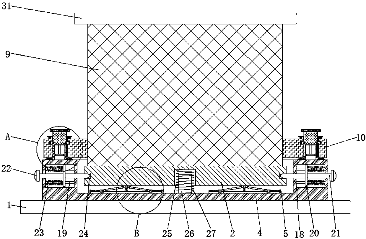
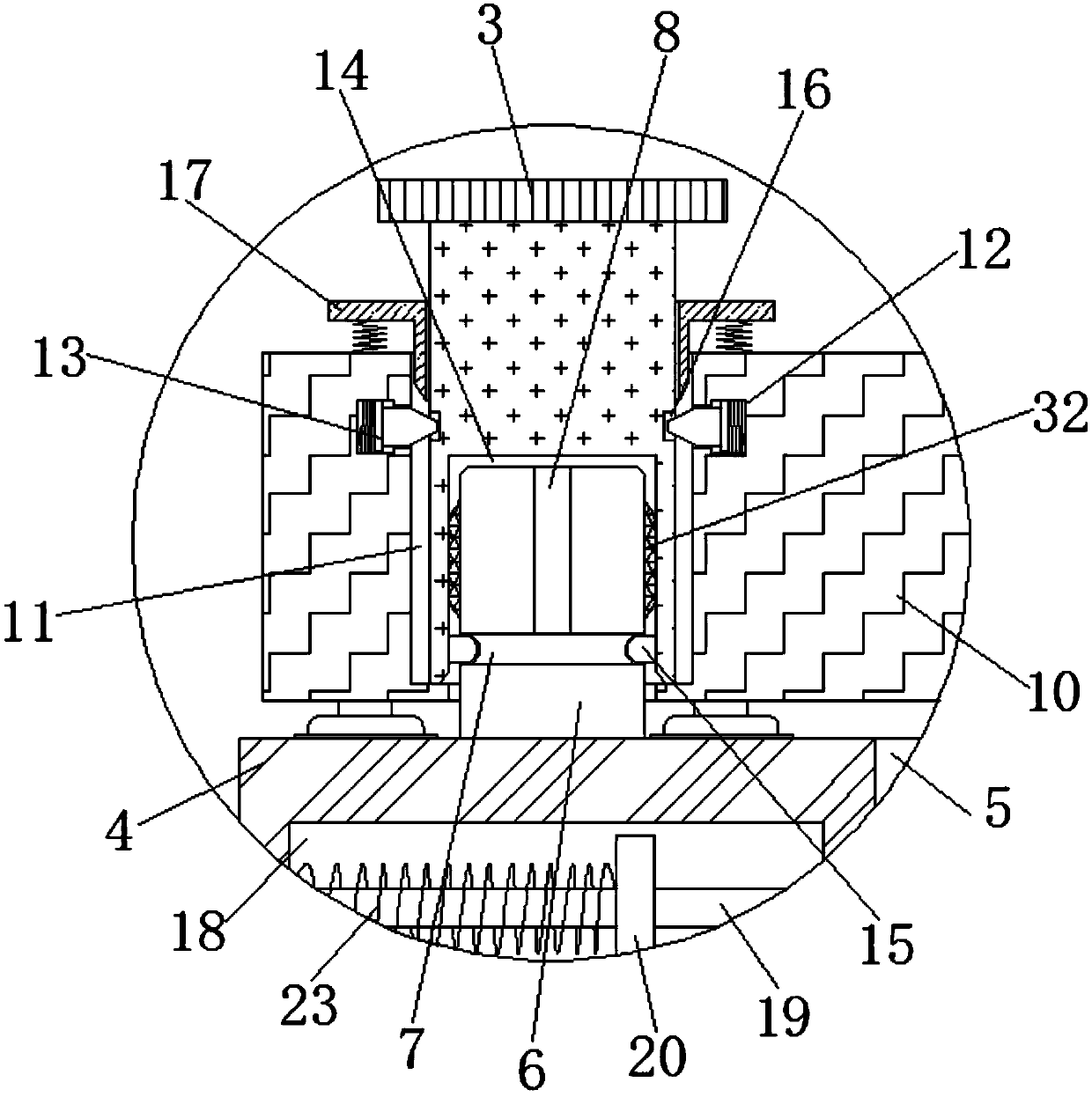
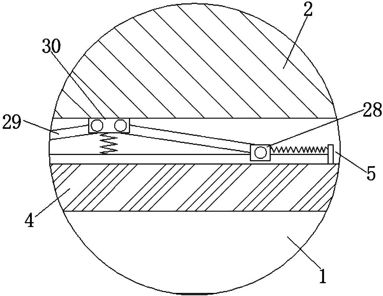
[0023] See Figure 1-3 , The present invention provides a technical solution: a quickly replaceable air filter element, comprising a fixed base 1, a fixed plate 2 and a connecting rod 3. The top of the fixed base 1 is fixedly connected with a mounting block 4, and the top of the mounting block 4 A mounting groove 5 is provided. The inside of the mounting block 4 and on both sides of the mounting groove 5 are provided with movable grooves 18. The top and bottom of one side of the inner wall of the movable groove 18 are fixedly connected to the top and bottom of the other side of the inner wall. There is a guide slide bar 19, and the outer surface of the guide slide bar 19 is slidably connected with a slide plate 20. One side of the slide plate 20 is fixedly connected with a positioning rod 21. One end of the positioning rod 21 penetrates the mounting groove 5 and extends to the mounting groove 5 Inside, the other end of the positioning rod 21 penetrates the mounting block 4 and extends to one side of the mounting block 4, and one end of the positioning rod 21 extending to one side of the mounting block 4 is fixedly connected with a slider 22. The function of the slider 22 makes people convenient Pull the positioning rod 21, between one side of the sliding plate 20 and one side of the inner wall of the movable groove 18 and located on the outer surface of the guide sliding rod 19, a return spring 23 is fixedly connected. The function of the return spring 23 makes it convenient to fix both sides of the plate 2. Each is provided with a positioning groove 24 adapted to the positioning rod 21, a buffer groove 25 is provided on the top of the fixing plate 2, a guide block 26 is fixedly connected to the bottom of the inner wall of the installation groove 5, and the top end of the guide block 26 penetrates the buffer groove 25 and Extending to the inside of the buffer groove 25, the outer surface of the guide block 26 is sleeved with a buffer spring 27. The buffer spring 27 has a good buffer effect. The bottom of the inner wall of the installation groove 5 is slidingly connected with a sliding block 28, and the top of the sliding block 28 A buffer rod 29 is slidably connected by a pin. The end of the buffer rod 29 away from the sliding block 28 is connected to a buffer block 30 through a pin rotation. The bottom of the buffer block 30 is fixedly connected to the bottom of the inner wall of the mounting groove 5 through a spring, and the top of the buffer block 30 In contact with the bottom of the fixed plate 2, the top of the mounting block 4 and both sides of the mounting groove 5 are fixedly connected with a fixed rod 6, and the outer surface of the fixed rod 6 is provided with an annular groove 7, and the outer surface of the fixed rod 6 is located The top of the annular groove 7 is provided with a guide groove 8, the top of the fixed plate 2 is fixedly connected with a filter element body 9, the top of the filter element body 9 is fixedly connected with a connecting plate 31, and the outer surface of the fixed rod 6 is fixedly connected with an elastic sealing gasket 32 , The elastic sealing washer 32 has a good sealing effect, and both sides of the filter core body 9 are fixedly connected with a connecting plate 10, and the top of the connecting plate 10 is provided with a fixing hole 11 that matches the fixing rod 6. The connecting plate 10 There are clamping grooves 12 inside and on both sides of the fixing hole 11, one side of the inner wall of the clamping groove 12 is fixedly connected with a T-shaped clamping head 13 through a clamping spring, and the bottom end of the connecting rod 3 penetrates the fixing hole 11 And extend to the inside of the fixing hole 11. The connecting rod 3 extends to the bottom of the fixing hole 11 and is provided with a fixing groove 14 which is adapted to the fixing rod 6. Both sides of the inner wall of the fixing groove 14 are fixedly connected with the annular groove 7 The two sides of the matching chuck 15 and the end of the connecting rod 3 extending to the inside of the fixing hole 11 are provided with grooves 16 that are compatible with the T-shaped chuck 13, and the top of the connecting plate 10 is located on the connecting socket. The outer surface of the rod 3 is fixedly connected with a T-shaped indenter 17 adapted to the T-shaped clamp 13 through a connecting spring, and the bottom of the T-shaped indenter 17 penetrates the fixing hole 11 and extends to the inside of the fixing hole 11.
[0024] It should be noted that in this article, relational terms such as first and second are only used to distinguish one entity or operation from another entity or operation, and do not necessarily require or imply one of these entities or operations. There is any such actual relationship or order between. Moreover, the terms "include", "include" or any other variants thereof are intended to cover non-exclusive inclusion, so that a process, method, article or device including a series of elements not only includes those elements, but also includes those that are not explicitly listed Other elements of, or also include elements inherent to this process, method, article or equipment.
[0025] Although the embodiments of the present invention have been shown and described, those of ordinary skill in the art can understand that various changes, modifications, and substitutions can be made to these embodiments without departing from the principle and spirit of the present invention. And variations, the scope of the present invention is defined by the appended claims and their equivalents.

PUM

no PUM

Description & Claims & Application Information

We can also present the details of the Description, Claims and Application information to help users get a comprehensive understanding of the technical details of the patent, such as background art, summary of invention, brief description of drawings, description of embodiments, and other original content. On the other hand, users can also determine the specific scope of protection of the technology through the list of claims; as well as understand the changes in the life cycle of the technology with the presentation of the patent timeline. Login to view more.

Similar technology patents

High-strength fracture-resistant loudspeaker frame

ActiveCN113242497AEasy to disassemblequick fix
Owner:ZHEJIANG OUSAI ELECTRONICS CO LTD

Electromagnetic flow measuring and adjusting instrument

PendingCN114109322Aquick fixEasy to disassemble
Owner:大庆科力远石油装备制造有限公司

Method for determining stress concentration coefficient of beveled end of stringer

PendingCN113051783AEasy way to determinequick fix
Owner:XIAN AIRCRAFT DESIGN INST OF AVIATION IND OF CHINA

Circuit board etching method

PendingCN114760764AImprove etch qualityquick fix
Owner:江西鸿宇电路科技有限公司

Classification and recommendation of technical efficacy words

  • quick fix
  • Reduce workload

Contaminated soil ex-situ medicating, mixing and restoring system

InactiveCN104368595Aquick fixReduced Diffusion of Disorder
Owner:CHINA CITY ENVIRONMENT PROTECTION ENGINEERING LIMITED COMPANY

Bionic bioceramic with through-hole structure and preparation method and application thereof

ActiveCN104606712Aquick fixPromotes transport and cell metabolism
Owner:GUANGZHOU HICARE DENTAL EQUIP & MATERIAL CO LTD

Device for detecting carrier communication in power consumption information collection device

InactiveCN104537828Ahelp work efficiencyquick fix
Owner:STATE GRID CORP OF CHINA +2

Liquid medicine for treating burn

InactiveCN102302595AQuick fixless susceptible to infection
Owner:于兰峰

Hospital gown

InactiveUS7181773B1reduce workloadquickly expose
Owner:WILLIAM BEAUMONT HOSPITAL

Performance Aware Peer-to-Peer Content-on-Demand

ActiveUS20090177792A1reduce workloadimproves perceive performance
Owner:THOMSON LICENSING SA

Method and apparatus for directionally grabbing page resource

InactiveCN101452463AIncrease yield and recallreduce workload
Owner:ZHEJIANG UNIV

Garbage classification prompt garbage can and system based on image recognition

InactiveCN107054936Areduce workloadachieve reuse
Owner:GUANGDONG MATVIEW INTELLIGENT SCI & TECH CO LTD

Construction site operation safety remote management and control system and method

InactiveCN107967562AReduce workloadSave human and material resources
Owner:TAIYUAN POWER SUPPLY COMPANY OF STATE GRID SHANXI ELECTRIC POWER +1
Why Eureka
Try Eureka