Tension device for automatic pipe welder and automatic pipe welder

A tensioning device and automatic welding technology, which is applied in the direction of auxiliary devices, welding equipment, auxiliary welding equipment, etc., can solve the problems of pipe fitting welding influence, reduce welding efficiency, and cannot guarantee welding quality, so as to ensure coaxiality, welding The effect of quality assurance

Inactive Publication Date: 2018-03-27
湖北峰佑高端装备制造有限公司
View PDF6 Cites 11 Cited by
  • Summary
  • Abstract
  • Description
  • Claims
  • Application Information

AI Technical Summary

Problems solved by technology

[0002] Although there is a unified pipe diameter standard in the existing pipe fittings industry, because the production equipment used by different manufacturers comes from different manufacturers, the pipe fittings processed by each manufacturer cannot be completely unified, which will result in pipe fittings. During the connection process (including the connection between pipe fittings and the connection between pipe fittings and elbows), even the inner diameters of pipe fittings with the same pipe diameter standard are not exactly the same, which has a great impact on the welding of pipe fittings
At present, for the welding of pipe fittings with the same pipe diameter and different inner diameters, it is mainly adjusted manually to the same inner diameter of the pipe fittings, and then the welding is completed by an automatic pipe welding machine, which greatly reduces the welding efficiency and cannot guarantee the welding quality.

Method used


Image

  • Tension device for automatic pipe welder and automatic pipe welder
  • Tension device for automatic pipe welder and automatic pipe welder
  • Tension device for automatic pipe welder and automatic pipe welder

Examples


Embodiment 1

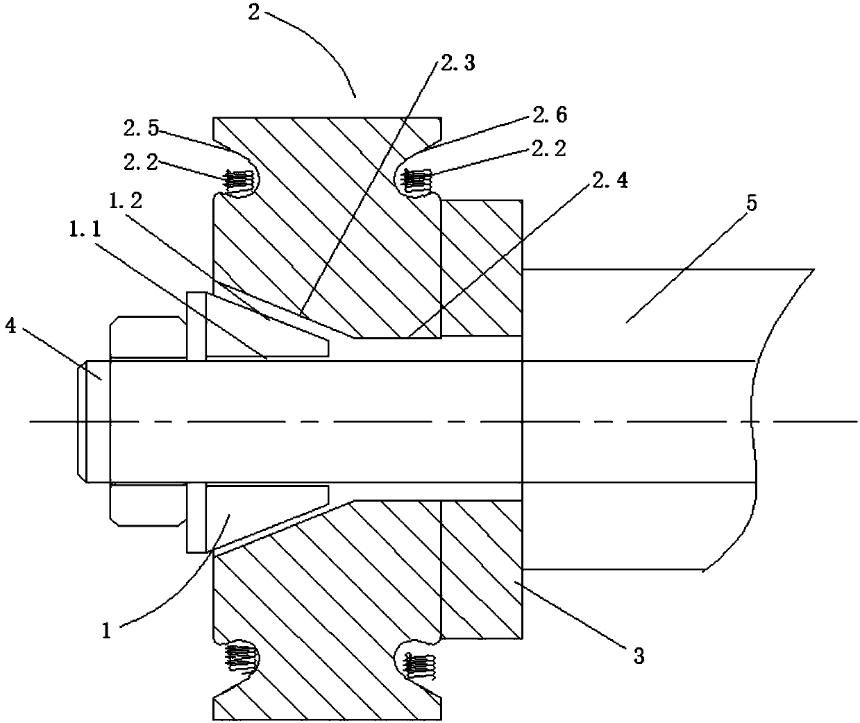
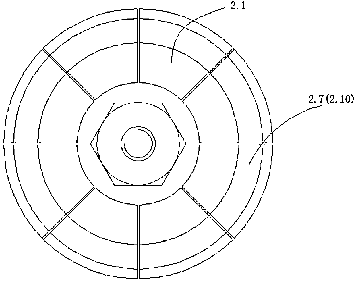
[0023] like Figures 1 to 2 As shown, the embodiment of the present invention provides a tensioning device for an automatic welded pipe machine. The tensioning device includes a conical top block 1 , an expansion sleeve 2 and a positioning platform 3 sequentially from front to back. In this embodiment, the middle part of the conical top block 1 is provided with a shaft hoop 1.1 matched with the inner rotating shaft 4 of the automatic pipe welding machine, and the rear end of the conical top block 1 is a conical body 1.2, wherein the conical top block The conical body 1.2 of 1 is sleeved into the expansion sleeve 2. The expansion sleeve 2 includes several arc-shaped expansion blocks 2.1, and several arc-shaped expansion blocks 2.1 are connected together by telescopic springs 2.2 to form the expansion sleeve 2. In this embodiment, the expansion sleeve 2 is composed of 8 arc-shaped The expansion block 2.1 is composed of 8 arc-shaped expansion blocks 2.1 through the telescopic sp...

Embodiment 2

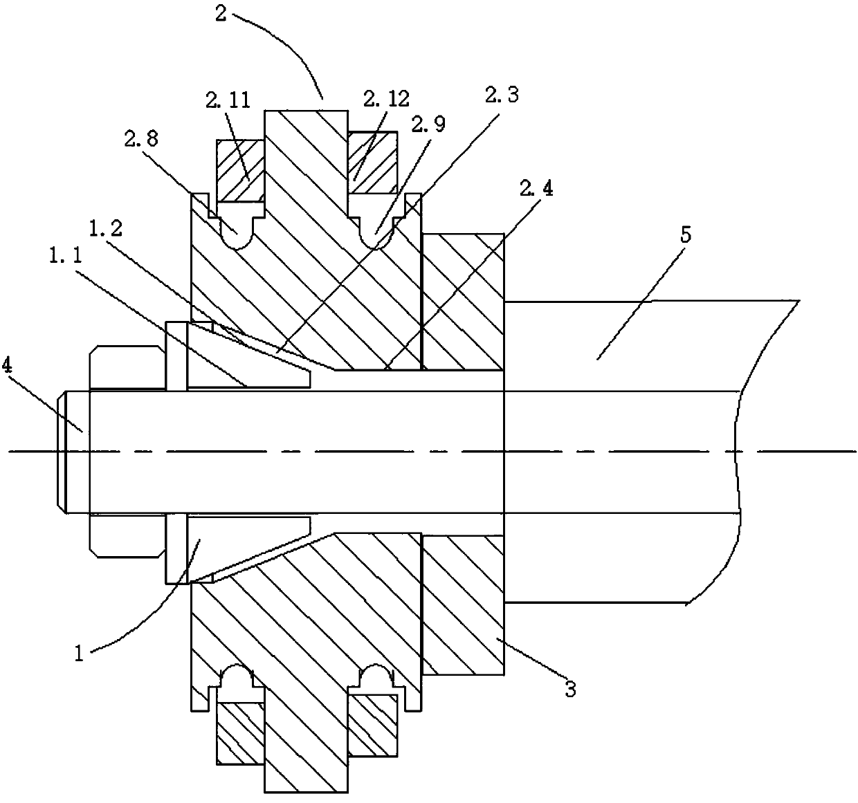
[0026] like image 3 As shown, the embodiment of the present invention provides a tensioning device for an automatic welded pipe machine. The tensioning device includes a conical top block 1 , an expansion sleeve 2 and a positioning platform 3 sequentially from front to back. In this embodiment, the middle part of the conical top block 1 is provided with a shaft hoop 1.1 matched with the inner rotating shaft 4 of the automatic pipe welding machine, and the rear end of the conical top block 1 is a conical body 1.2, wherein the conical top block The conical body 1.2 of 1 is sleeved into the expansion sleeve 2. The expansion sleeve 2 includes several arc-shaped expansion blocks 2.1, and several arc-shaped expansion blocks 2.1 are connected together by telescopic springs 2.2 to form the expansion sleeve 2. In this embodiment, the expansion sleeve 2 is composed of 8 arc-shaped The expansion block 2.1 is composed of 8 arc-shaped expansion blocks 2.1 through the telescopic spring 2....


PUM


Abstract

The invention discloses a tension device for an automatic pipe welder. The tension device comprises a conical ejector block, a tension sleeve and a positioning platform from front to back in sequence;the middle of the conical ejector block is provided with a shaft clip matched with an inner rotary shaft, and the rear end of the conical ejector block is a conical surface body; the tension sleeve comprises a plurality of arc-shaped tension blocks, and the multiple arc-shaped tension blocks are connected together through telescopic springs to form the tension sleeve; the inner wall of the tension sleeve comprises a wedge surface matched with the conical surface body, and a columnar surface connected with an outer rotary shaft; and the rear end face of the tension sleeve makes contact with the positioning platform. Through the tension device, when two pipes which need to be subjected to butt welding and have the same pipe diameter standard are different in inner diameter, the two pipes are subjected to butt joint to sleeve the tension sleeve, the inner diameters of the two pipes can be adjusted to be the same through the tension sleeve, and the butt welding quality is ensured.

Description

technical field [0001] The invention relates to the technical field of automatic pipe welding machines, in particular to a tensioning device for automatic pipe welding machines and the automatic pipe welding machine thereof. Background technique [0002] Although there is a unified pipe diameter standard in the existing pipe fittings industry, because the production equipment used by different manufacturers comes from different manufacturers, the pipe fittings processed by each manufacturer cannot be completely unified, which will result in pipe fittings. During the connection process (including the connection between pipe fittings and the connection between pipe fittings and elbows), even the inner diameters of pipe fittings with the same pipe diameter standard are not exactly the same, which has a great impact on the welding of pipe fittings. At present, for the welding of pipe fittings with the same pipe diameter standard and different inner diameters, it is mainly adjust...

Claims


Application Information

Patent Timeline
Patent Type & Authority Applications(China)
IPC IPC(8): B23K37/053
CPCB23K37/0531
Inventor 曾来运
Owner 湖北峰佑高端装备制造有限公司
Why Eureka
Try Eureka