Deflashing device

A technology for removing flashes and workpieces, which is applied in the field of devices for removing flashes of non-metallic materials. It can solve the problems of reducing the working efficiency of the motor, affecting the appearance of the product, and troublesome disassembly and replacement. It is convenient for daily maintenance and replacement of parts, and convenient for statistical work. Quantity, the effect of improving the efficiency of use

Active Publication Date: 2018-03-27
SOUTHWEAT UNIV OF SCI & TECH
View PDF4 Cites 0 Cited by
  • Summary
  • Abstract
  • Description
  • Claims
  • Application Information

AI Technical Summary

Problems solved by technology

The existence of flashing not only affects the appearance of the product, but also has certain safety hazards in the process of use. Therefore, it is necessary to remove the flashing after the processing is completed.
[0003] At present, in the machining industry, there are some problems. For example, when the cutting frame is damaged, it is troublesome to disassemble and replace; the motor will generate a lot of heat when it is in motion. work efficiency

Method used


Image

  • Deflashing device
  • Deflashing device
  • Deflashing device

Examples


Embodiment Construction

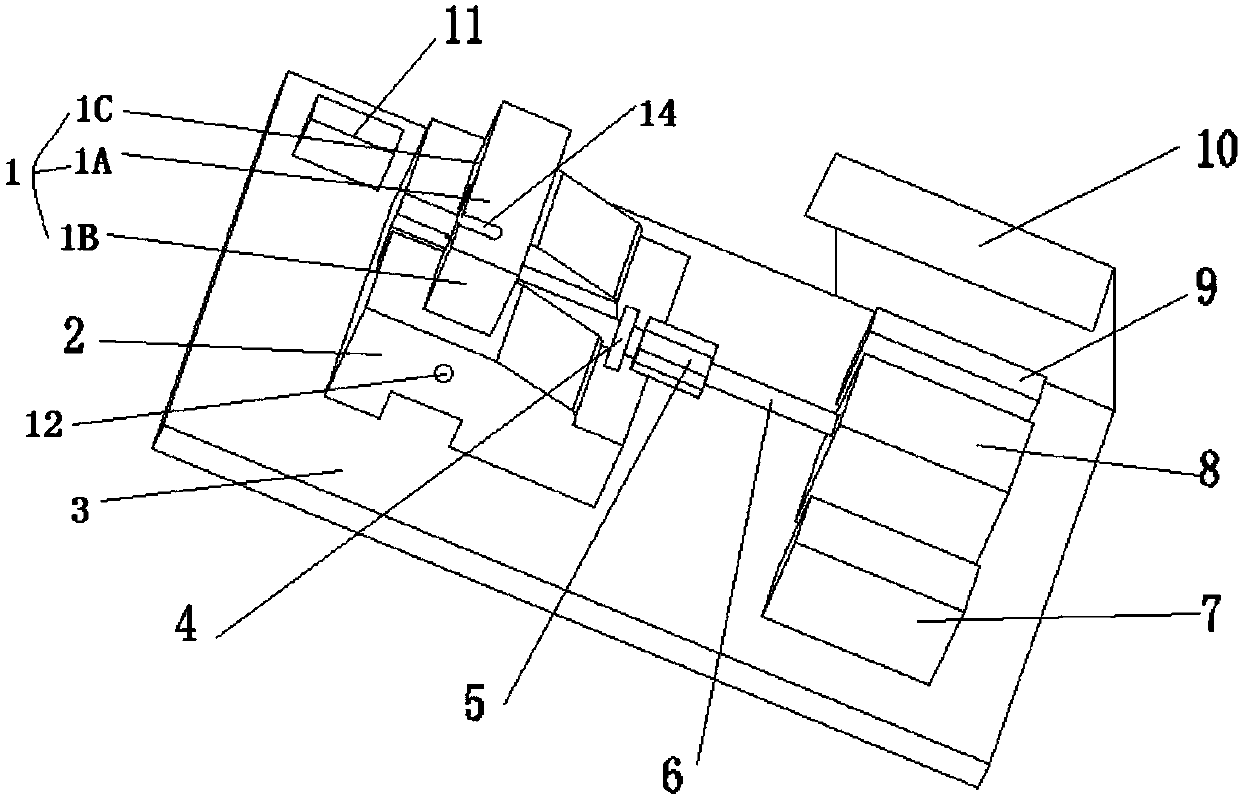
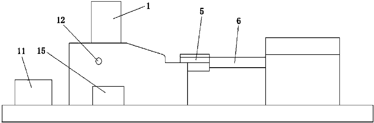
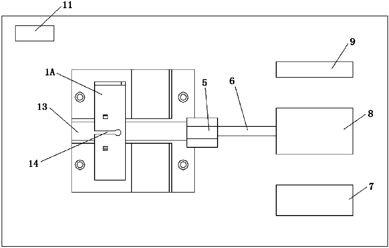
[0023] In the following detailed description, the deflashing device of the present invention will be described in detail with reference to the accompanying drawings and exemplary embodiments.

[0024] In an exemplary embodiment of the present invention, the deflashing device may include a cutting unit, a guiding unit, and a power unit for driving the guiding unit. Wherein, the cutting unit comprises a channel for the workpiece to pass through and a deburring knife positioned on the inner wall of the channel, the cutting edge of the deburring knife is arranged perpendicular to the moving direction of the workpiece and acts on the surface of the workpiece to remove the workpiece when the workpiece passes through the channel The flash on the surface, the guide unit includes a push rod and a push block for pushing the workpiece, the front end of the push rod is connected with the top block, and the rear end of the push rod is connected with the power unit. The shape of the deburri...


PUM


Abstract

The invention provides a deflashing device. The deflashing device comprises a cutting unit, a guide unit and a power unit for driving the guide unit, wherein the cutting unit comprises a channel through which a workpiece passes and a deflashing tool located on the inner wall of the channel; a cutting edge of the deflashing tool is arranged along a direction perpendicular to the moving direction ofthe workpiece, and acts on the surface of the workpiece when the workpiece passes through the channel to remove flashes of the surface of the workpiece; the guide unit comprises an ejector pin and anejection block for pushing the workpiece; the front end of the ejector pin is connected with the ejection block; and the rear end of the ejector pin is connected with the power unit. According to thedeflashing device provided by the invention, by arrangement of a heat dissipation device, the use efficiency of equipment is improved; the deflashing device is simple and practical in structure, lowin cost and high in cost performance; a cutting rack and a tool bracket are mounted in a simple way, and daily maintenance and replacement of parts are facilitated; and a counting switch is mounted, so that the work amount is convenient to count.

Description

technical field [0001] The invention belongs to the field of non-metal processing, and in particular relates to a device for removing non-metal material (such as plastic) flash. Background technique [0002] With the development of mechanical technology, non-metallic workpieces are more and more widely used in the mechanical industry. However, in the die-casting process of non-metallic workpieces, because there is inevitably a certain gap between the movable mold and the fixed mold, some non-metallic fluids will flow into the gap to form redundant sheet corners, and the workpiece processing process The thorns or flashes formed around the processed parts of the machine, commonly known as flashes. The existence of flashing not only affects the appearance of the product, but also poses certain safety hazards during use. Therefore, it is necessary to remove flashing after processing. [0003] At present, in the machining industry, there are some problems. For example, when the...

Claims


Application Information

Patent Timeline
Patent Type & Authority Applications(China)
IPC IPC(8): B29C37/02
CPCB29C45/0053B29C2045/0077
Inventor 杨应洪刘越邓洪权尹显明王银玲倪磊孟慧玲陈玥罗盆琳朱利祯何春林张秘
Owner SOUTHWEAT UNIV OF SCI & TECH
Why Eureka
Try Eureka