Micro switch with positive separation mechanism

A separation mechanism and micro switch technology, applied in the direction of electric switches, electrical components, circuits, etc., can solve the problems of switch application restrictions, permanent deformation of moving contacts, switch elastic attenuation, etc., to ensure electrical safety, the material of moving contacts The effect of thickening the thickness and preventing the deformation of the material

Active Publication Date: 2020-06-30
ZHANGZHOU JUANMEI ELECTRIC TECH CO LTD
View PDF13 Cites 0 Cited by
  • Summary
  • Abstract
  • Description
  • Claims
  • Application Information

AI Technical Summary

Problems solved by technology

[0005] 1. Most of the micro switches are self-resetting by tension springs, reeds or integral shrapnel. In the initial state, the contact on the moving contact piece of the switch is usually in contact with the contact on the normally closed connector. The rocker movement mode is used to realize the forced separation of the switch. When the contact on the movable contact piece contacts the contact on the normally closed connector at the top, one end of the forced separation part moves downward around the fulcrum when the button is pressed down, and the other end of the forced separation part moves The direction is upward, and the forced separation can only be forced to separate when it acts on the moving contact piece downwards. Therefore, the movement direction of the other end of the forced separation is upward and does not work, which also makes it difficult for the micro switch to realize the forced separation function.
[0006] 2. The internal elastic parts of the micro switch mostly use tension springs, and the reeds or integral shrapnel trigger the switch to turn on and off. The switching action and reset are all completed by the elastic parts. The elasticity of the elastic parts is generally relatively small. The forced separation part cannot be reset by itself, and it needs to be reset by the elastic force of the switch shrapnel, but the elastic force of the elastic part of the micro switch is generally too small, and additional force is required to force the separation part to reset, which increases the burden on the elastic part and easily affects the switching characteristics. , the switch elastic attenuation, severe cases can lead to switch action failure, if the switch is installed in a vibrating environment, the vibration of the forced separation part is also likely to cause problems
[0007] 3. When the micro switch adopts reed or integral shrapnel, because the wall thickness of the moving contact piece itself is thin and elastic, when the forced separation part acts on the elastic moving contact piece, because the action stroke of the micro switch is relatively short, the moving The elastic deformation of the contact piece offsets the function of the forced separation part, which will cause the forced separation part to not work. To solve this problem, the total stroke of the switch needs to be increased, but the limited space of the micro switch does not allow any further increase of the stroke, otherwise the switch will become non-standard. Switch, even if it is allowed to increase the total stroke of the switch, because most of the micro switches are reset by the reed or integral shrapnel, the increase of the total stroke will cause the moving contact piece to fall out of the groove and the switch will not be able to operate
Even if the moving contact piece does not fall off, because the gap between the dynamic and static contacts of the micro switch is relatively small, when the switch contact is forced to separate and acts on the elastic moving contact piece, the stroke is large, and it is easy to cause permanent deformation of the moving contact piece. Deformation will lead to shape changes, and shape changes will lead to changes in the position of the fulcrum of the moving contact piece, resulting in changes in the parameters of the switch action, which will seriously cause the switch to fail to operate or reset
[0008] One or more of the above problems lead to the fact that the same type or similar micro switches with forced separation function are basically not seen in the market, which belongs to the bottleneck of the micro switch industry. The switch does not have the forced separation function. The point cannot be separated normally during the button pressing process, which sometimes brings serious safety hazards. Because the existing micro switch cannot realize forced separation, it cannot be applied to fields with safety requirements, especially in some industries with industry standards, such as elevators. Industry etc.
As a result, the switch application is strictly restricted, restricting the development of the industry

Method used


Image

  • Micro switch with positive separation mechanism
  • Micro switch with positive separation mechanism
  • Micro switch with positive separation mechanism

Examples


Embodiment 1

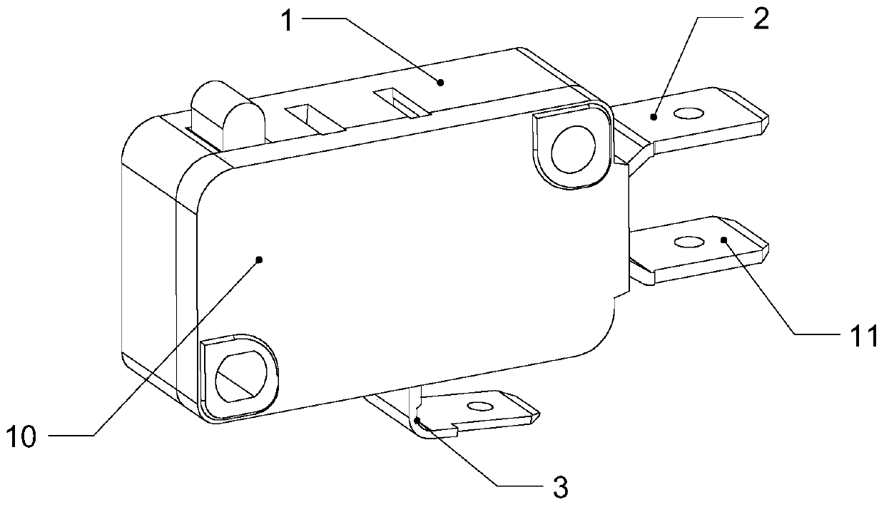
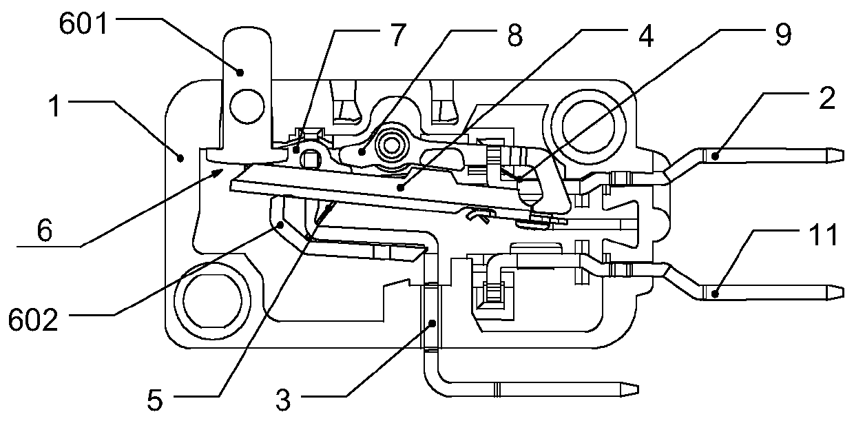
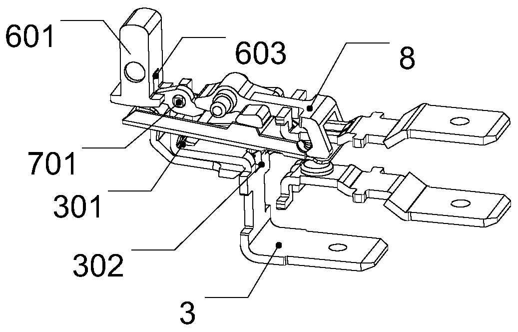
[0075] Such as figure 1 and figure 2 As shown, a micro switch with a forced separation mechanism of the present invention includes a housing 1 and a cover plate 10 adapted to the housing 1, and the housing is provided with a normally closed connector 2, a common connector 3, The normally open connector 11, the movable contact piece 4, the elastic member 5, the trigger assembly 6 and the forced separation mechanism for forcibly separating the moving and static contacts of the multi-stage transmission. One end of the normally open connector 11 , the normally closed connector 2 and the common connector 3 is located inside the housing 1 , and one end extends out of the housing 1 . The movable contact piece 4 is electrically connected with the public connector 3, and has a movable contact that can communicate with the static contact of the normally closed connector 2; The elastic member 5 and the trigger assembly 6. The elastic member 5 is a reed. One end of the reed abuts agai...

Embodiment 2

[0084] Such as Figure 9 and Figure 10 As shown, the structure of embodiment 2 is the same as that of embodiment 1, the difference is that the elastic member 5 of the present invention is a reed that forms an integral structure with the movable contact 4, and one end of the reed is fixed to the movable contact 4 The upper end and the other end are freely cantilevered, and the free cantilever end of the reed abuts against the first notch 301 of the public connector 3 . Such as Figure 11 and Figure 12 As shown, the moving contact piece 4 includes a moving contact piece base 401 and a contact structure 402 located on the moving contact piece base 401 as a moving contact. The movable contact piece base 401 is a sheet structure with a hollowed-out area in the middle. The hollowed-out area on the side of the sheet structure close to the contact structure 402 is fixedly connected with one end of the reed, and the hollowed-out area near the free cantilever end of the reed is con...

Embodiment 3

[0087] Such as Figure 13 and Figure 14 As shown, the structure of embodiment 3 is the same as that of embodiment 1, the difference is that the elastic member 5 is a tension spring, one end of the tension spring is hooked on the moving contact piece 4, and the other end is hooked on the first support member 602 superior. The movable contact piece 4 and the first supporting member 602 can respectively have connection notches matching with the extension springs. The moving contact piece 4 includes a moving contact piece base 401 and a contact structure 402 on the moving contact piece base 401 serving as a moving contact; and there is no need to add flanges and gaskets.

[0088] Working process: same as embodiment 1.


PUM


Abstract

The invention discloses a microswitch with a forced separating mechanism, and the microswitch comprises a housing. The interior of the housing is provided with a normally-closed connector assembly anda common connector assembly and also comprises an elastic assembly which is electrically connected with the common connector assembly and can be electrically connected with the normally-closed connector assembly. The elastic assembly is linked with a triggering assembly, and can swing around a supporting part of the common connector assembly under the action of the triggering assembly. The interior of the housing is also provided with the multi-stage transmission forced separating mechanism, and the forced separating mechanism can make contact with the elastic assembly under the action of thetriggering assembly, and can separate the elastic assembly with the normally-closed connector assembly in a forced manner. The microswitch is provided with the forced separating mechanism. When the microswitch has an abnormality and the contact of a static contact of the normally-closed connector assembly with a moving contact on the common connector assembly is not normally cut off, the forced separating part will separate the moving and static contacts in a forced manner, so as to guarantee the electrical safety.

Description

technical field [0001] The invention relates to a switch, in particular to a micro switch with a forced separation mechanism. Background technique [0002] The micro switch is a contact mechanism with a small contact interval and a quick-action mechanism, which performs switching actions with a specified stroke and a specified force. It is covered with a casing and has a trigger rod on the outside. Small, hence the name micro switch. The external mechanical force acts on the action reed through the transmission element (press pin, button, lever, roller, etc.). Tap to quickly connect or disconnect. When the force on the transmission element is removed, the action reed produces a reverse action force, and when the reverse stroke of the transmission element reaches the action critical point of the reed, the reverse action is completed instantaneously. The contact spacing of the micro switch is small, the action stroke is short, the pressing force is small, and the on-off is ...

Claims


Application Information

Patent Timeline
Patent Type & Authority Patents(China)
IPC IPC(8): H01H13/20H01H13/12
CPCH01H13/12H01H13/20
Inventor 戴四川
Owner ZHANGZHOU JUANMEI ELECTRIC TECH CO LTD
Why Eureka
Try Eureka