
Composite substrate type microstrip circulator

A technology of composite substrates and circulators, which is applied in waveguide devices, electrical components, circuits, etc., to achieve the effects of reducing loss, easy preparation and assembly of devices, and ensuring tight integration

Active Publication Date: 2018-03-27
BEIJING INST OF RADIO MEASUREMENT
View PDF9 Cites 24 Cited by
  • Summary
  • Abstract
  • Description
  • Claims
  • Application Information

AI Technical Summary

Benefits of technology

This technology improves upon previous designs by reducing their sizes while maintaining good electrical performance for use at higher frequencies than previously possible due to its ability to compress it more effectively without losing any magnetism during manufacturing processes. Additionally, this design allows for better integration between both materials when they form together.

Problems solved by technology

This patents discuss various technical problem addressed by this patented technology: how to improve the design of small wave devices called Microtor Circulators for both forward and backward signals while maintaining good electrical characteristics such as low loss tangential current flow when they operate at higher frequencies.

Method used


Image

  • Composite substrate type microstrip circulator
  • Composite substrate type microstrip circulator
  • Composite substrate type microstrip circulator

Examples


Embodiment 1

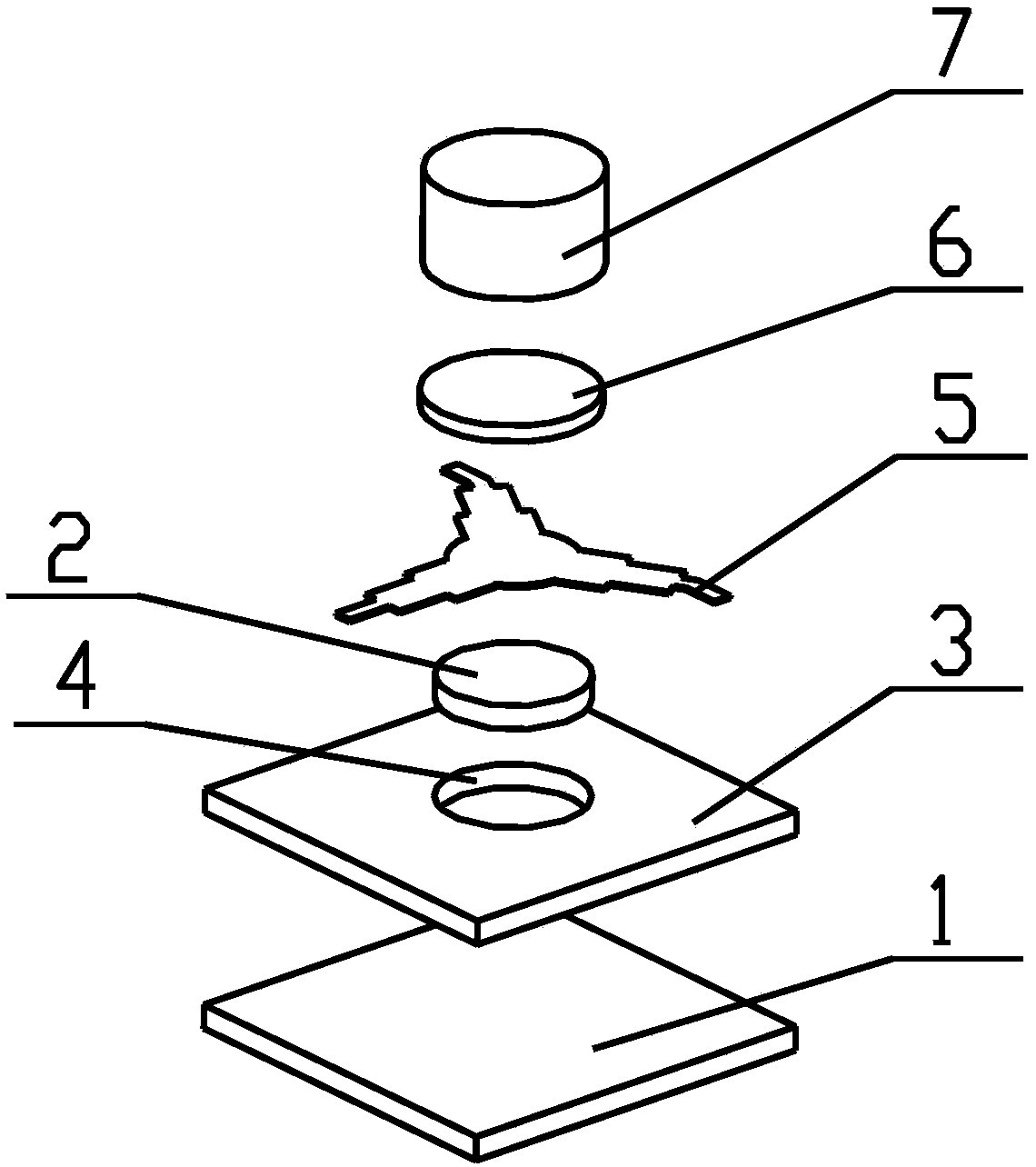
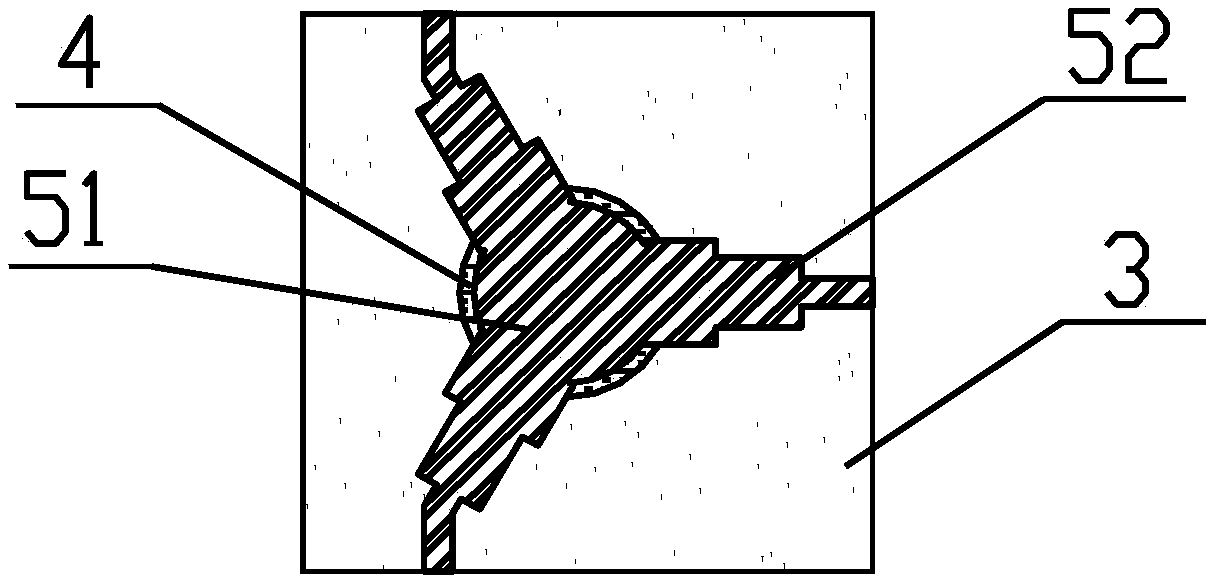
[0038] Such as figure 1 with figure 2 As shown, the specific implementation of the composite substrate microstrip circulator works in the C-band, with a center frequency of 4.5GHz; the dielectric substrate in the composite substrate is made of high dielectric constant composite ceramics, and the thickness of the dielectric substrate is 0.5mm. The dielectric constant of the substrate is about 40; the through hole on the dielectric substrate is prepared by mechanical drilling technology, and the through hole is circular with a diameter of 3.05 mm; the ferrite substrate in the composite substrate is circular with a diameter of 3.05 mm. 3mm, dielectric constant 13, saturation magnetization 1500Gs.

[0039] During the preparation process, the circular ferrite substrate is embedded in the through hole on the dielectric substrate, and the sealing glass is filled in the gap between the ferrite substrate and the dielectric substrate. Through low-temperature co-firing, the ferrite subst...

Embodiment 2

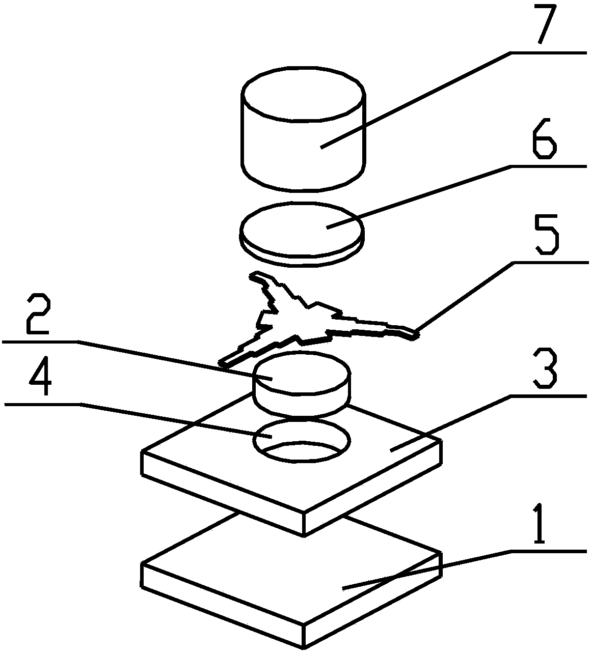
[0047] Such as image 3 with Figure 4 As shown, the specific implementation of the composite substrate microstrip circulator works in the X-band, with a center frequency of 9.5GHz; the dielectric substrate in the composite substrate is made of high dielectric constant composite ceramics, and the thickness of the dielectric substrate is 0.5mm. The dielectric constant of the substrate is about 40; the through hole on the dielectric substrate is prepared by mechanical drilling technology, and the through hole is circular with a diameter of 1.65 mm; the ferrite substrate in the composite substrate is circular with a diameter of 1.65 mm. 1.6mm, dielectric constant 12.5, saturation magnetization 2200Gs.

[0048] During the preparation process, the circular ferrite substrate is embedded in the through hole on the dielectric substrate, and the sealing glass is filled in the gap between the ferrite substrate and the dielectric substrate. Through low-temperature co-firing, the ferrite...


PUM

PropertyMeasurementUnit
Thicknessaaaaaaaaaa
Diameteraaaaaaaaaa
Saturation magnetizationaaaaaaaaaa

Abstract

The present invention provides a composite substrate type microstrip circulator. The composite substrate type microstrip circulator comprises a ferrite-dielectric substrate composed of a ferrite substrate and a dielectric substrate; a through hole is formed in the dielectric substrate; the ferrite substrate is fixed in the through hole in the dielectric substrate; the upper and lower surface of the ferrite-dielectric substrate are plated with metal layers; the upper surface of the ferrite-dielectric substrate is provided with a microstrip circuit; the lower surface of the ferrite-dielectric substrate is provided with a continuous metal layer; an annular junction region microstrip circuit in the microstrip circuit is disposed on the ferrite substrate; a matching microstrip circuit in the microstrip circuit is disposed on the dielectric substrate; a ceramic spacer and a permanent capacitor are disposed above the microstrip circuit; and the ferrite-dielectric substrate is fixed on a metalbase. Compared with a traditional full-ferrite substrate type microstrip circulator, the composite substrate type microstrip circulator has the advantages of small size and low consumption, and is applicable to surface mounted and highly integrated microwave circuits.

Description


Claims


Application Information

Patent Timeline
Owner BEIJING INST OF RADIO MEASUREMENT
Learn More