Method and device for adjusting transmit power in UE and base station
A power adjustment and center frequency technology, applied in the field of transmission power adjustment, can solve problems such as subcarrier interference, destruction of subcarrier orthogonality, interference, etc.
- Summary
- Abstract
- Description
- Claims
- Application Information
AI Technical Summary
Problems solved by technology
Method used
Image
Examples
Embodiment 1
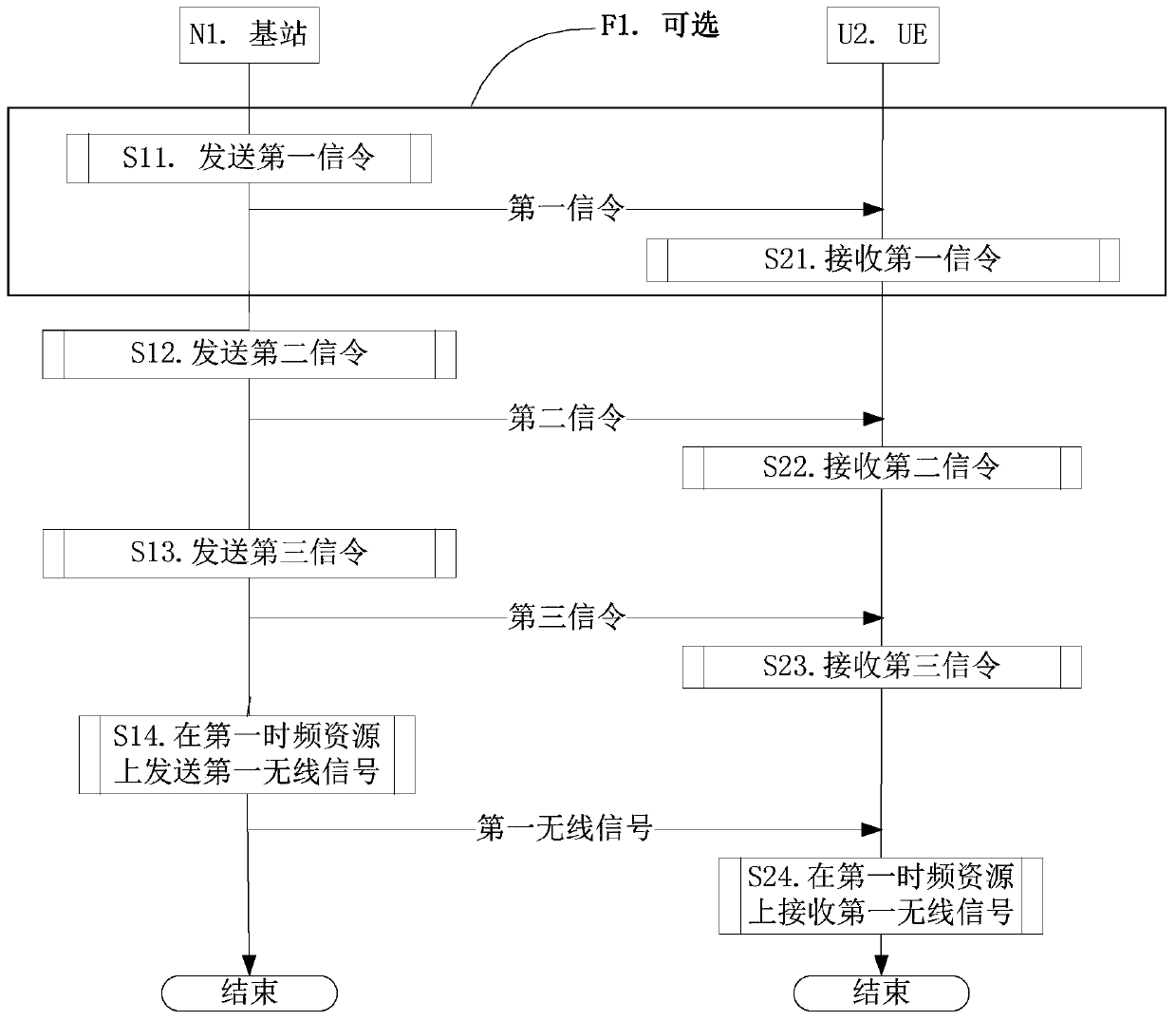
[0170] Embodiment 1 illustrates the flow chart of wireless signal downlink transmission, as shown in the attached figure 1 shown. attached figure 1 In , base station N1 is the maintenance base station of the serving cell of UE U2, and the steps identified in block F1 are optional.
[0171] for base station N1 , sending the first signaling in step S11, sending the second signaling in step S12, sending the third signaling in step S13, and sending the first wireless signal on the first time-frequency resource in step S14.
[0172] for UE U2 , receiving the first signaling in step S21, receiving the second signaling in step S22, receiving the third signaling in step S23, and receiving the first wireless signal on the first time-frequency source in step S24.
[0173] In Embodiment 1, the first time-frequency resource includes a first sub-time-frequency resource and a second sub-time-frequency resource. The normalized transmission energy of each RU in the first sub-time-frequ...
Embodiment 2
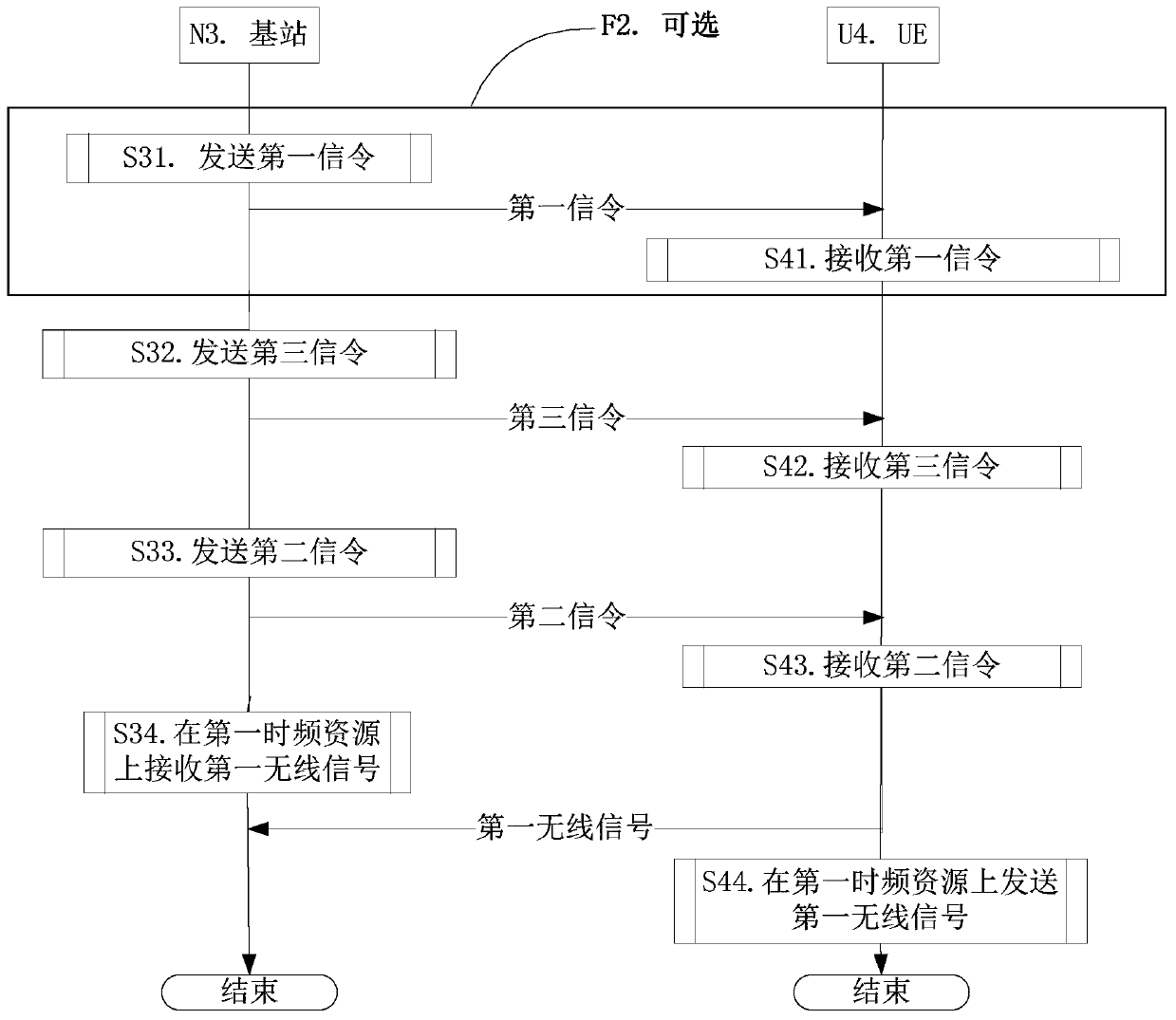
[0186] Embodiment 2 illustrates the schematic diagram of the first time window, as attached figure 2 shown. in the attached figure 2 In , base station N3 is the maintenance base station of the serving cell of UE U4, and the steps identified in block F2 are optional.
[0187] for base station N3 , sending the first signaling in step S31, sending the third signaling in step S32, sending the second signaling in step S33, and receiving the first wireless signal on the first time-frequency resource in step S14.
[0188] for UE U4 , receiving the first signaling in step S41, receiving the third signaling in step S42, receiving the second signaling in step S43, and sending the first wireless signal on the first time-frequency source in step S44.
[0189] In Embodiment 2, wherein the first time-frequency resource includes a first sub-time-frequency resource and a second sub-time-frequency resource. The normalized transmission energy of each RU in the first sub-time-frequency ...
Embodiment 3
[0204] Embodiment 3 illustrates a schematic diagram of the relationship between the first sub-time-frequency resource and the second sub-time-frequency resource, as shown in the attached image 3 shown. in the attached image 3 , the horizontal axis represents time, the vertical axis represents frequency, the area filled with oblique lines represents the first sub-time-frequency resource, and the area filled with vertical lines represents the second sub-time-frequency source. In Embodiment 3, the first time-frequency resource includes a first sub-time-frequency resource and a second sub-time-frequency resource, the first sub-time-frequency resource is different from the second sub-time-frequency resource, and the first sub-time-frequency resource The time-frequency resource and the second sub-time-frequency resource occupy the same time interval in the time domain.
[0205] In sub-embodiment 1 of embodiment 3, the subcarrier spacing in the first time-frequency resource is eq...
PUM
 Abstract
Description
Claims
Application Information
 - R&D
- Intellectual Property
- Life Sciences
- Materials
- Tech Scout
- Unparalleled Data Quality
- Higher Quality Content
- 60% Fewer Hallucinations
Browse by: Latest US Patents, China's latest patents, Technical Efficacy Thesaurus, Application Domain, Technology Topic, Popular Technical Reports.
© 2025 PatSnap. All rights reserved.Legal|Privacy policy|Modern Slavery Act Transparency Statement|Sitemap|About US| Contact US: help@patsnap.com


