
Space-saving ratchet unit with freewheel

A ratchet and flywheel technology, applied in the field of space-saving ratchet units with flywheels, can solve problems such as instability, and achieve the effect of reducing radial space requirements

Active Publication Date: 2018-03-27
AESCULAP AG
View PDF10 Cites 1 Cited by
  • Summary
  • Abstract
  • Description
  • Claims
  • Application Information

AI Technical Summary

Problems solved by technology

However, reintroduction of the latter is often unstable

Method used


Image

  • Space-saving ratchet unit with freewheel
  • Space-saving ratchet unit with freewheel
  • Space-saving ratchet unit with freewheel

Examples


Embodiment Construction

[0060] The drawings are only schematic and are used to aid understanding of the present invention. The same elements are denoted by the same reference numerals.

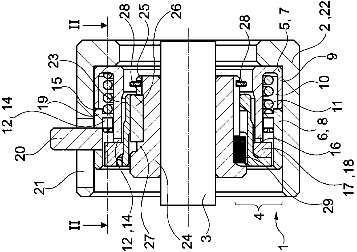
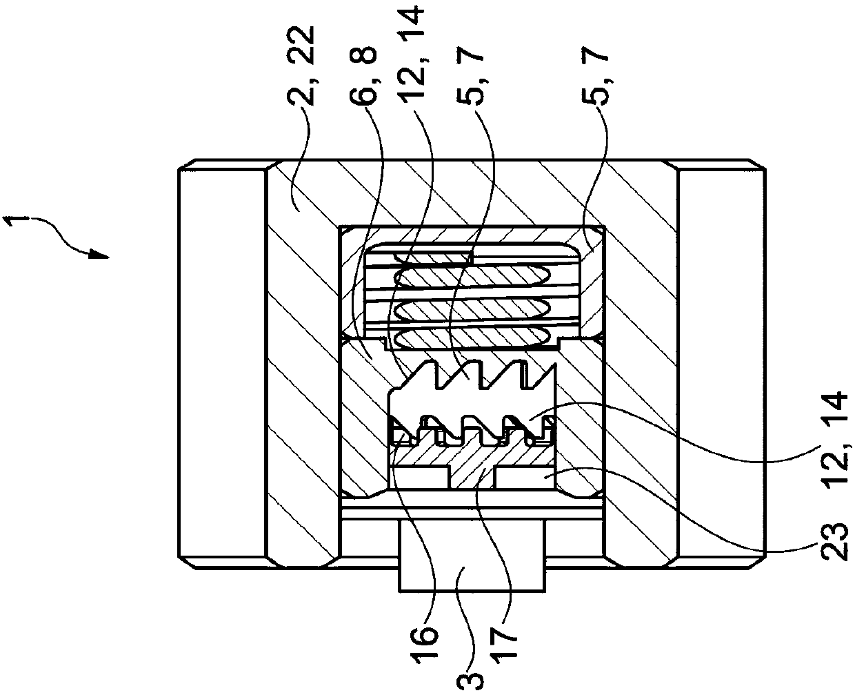
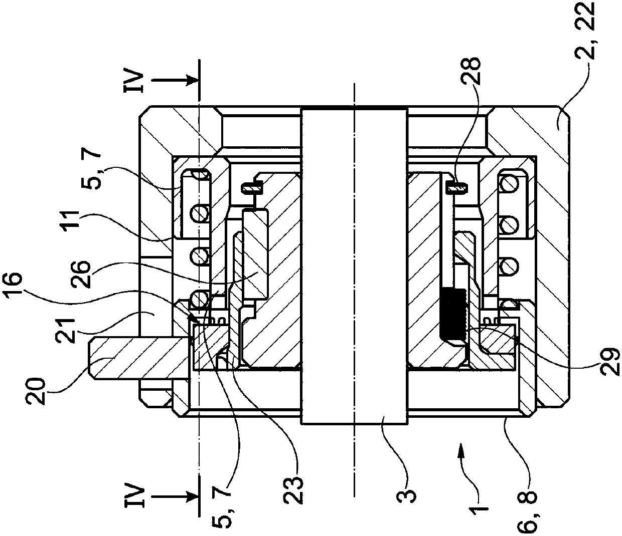
[0061] figure 1 A ratchet 1 according to the invention is shown. Said ratchet 1 , which can also be called ratchet or ratchet, is in switching position 1 in order to ensure right-hand rotation. It has a torque introducing or input element (input sleeve / ratchet housing) 2 and a torque releasing or output element (output sleeve / output shaft) 3 . A toothed unit (ratchet transmission) 4 is arranged between the two components 2 and 3 . Preferably, the toothed unit 4 can be switched manually. Depending on the switching position of the toothed unit 4 , torque is or can be transmitted from the torque vectoring element 2 to the torque release element 3 in the direction of rotation selected corresponding to the switching position. Depending on the switching position and the direction of rotation on the torque vectoring el...


PUM


Abstract

The invention relates to a ratchet (1) for a medical device (30), comprising a torque-guiding element (2) and a torque discharging element (3), between which a switchable toothed unit (4) is arrangedso that, in accordance with a switching position of the toothed unit (4), torque from the torque-guiding element (2) is transferred to the torque discharging element, said toothed unit (4) comprises two torque transfer sleeves (5, 6) arranged in a nested manner and which are arranged and produced such that both can be brought into torque-transmitting contact with an intermediate sleeve (17). The invention also relates to a medical device (30) comprising a ratchet of said type (1).

Description

technical field [0001] The present invention relates to a ratchet for medical devices such as drilling, milling and / or screwing machines for drilling / milling bone and / or for setting screws in bone or for screwing in implants, The ratchet comprises a torque vectoring element and a torque releasing element, between which a switchable toothed unit is arranged such that, depending on the switched position of the toothed unit, the torque from the torque vectoring element is only transmitted in a selectable one direction of rotation to Torque release element. Background technique [0002] A close prior art is known, for example, from DE 10 2011 088 252 A1. This document discloses an additional ratchet for driving a tightening tool for loosening and tightening screw elements and which can be driven selectively in two directions of rotation, optionally the additional ratchet can be realized as a straight The additional section can also be realized as an angular additional section....

Claims


Application Information

Patent Timeline
Patent Type & Authority Applications(China)
IPC IPC(8): A61B17/16A61B17/84B25B15/04A61B17/00
CPCA61B17/162A61B17/1624A61B2017/00407A61B17/84B25B13/466B25B23/141
Inventor 简·施泰因豪泽拉尔夫·菲斯特
Owner AESCULAP AG
Learn More