Mobile communication system, mobile station device, base station device, communication method, and communication control method

A technology of a mobile communication system and a control method, which is applied to the control field of handover in mobile communication, can solve the problems of unclear control procedures, ignoring synchronization time, unclear control procedures of mobile station devices, etc.

Inactive Publication Date: 2010-09-01
SHARP KK
View PDF3 Cites 11 Cited by
  • Summary
  • Abstract
  • Description
  • Claims
  • Application Information

AI Technical Summary

Problems solved by technology

There is also the problem of not taking into account the timing of maintaining uplink synchronization, and the problem of unclear control procedures when signals sent at the time of uplink or downlink resource allocation cannot be received
In addition, there is a problem that when a handover execution time is specified and a handover instruction message is received after the specified handover execution time, the control procedure of the mobile station device is unclear

Method used


Image

  • Mobile communication system, mobile station device, base station device, communication method, and communication control method
  • Mobile communication system, mobile station device, base station device, communication method, and communication control method
  • Mobile communication system, mobile station device, base station device, communication method, and communication control method

Examples


example 1

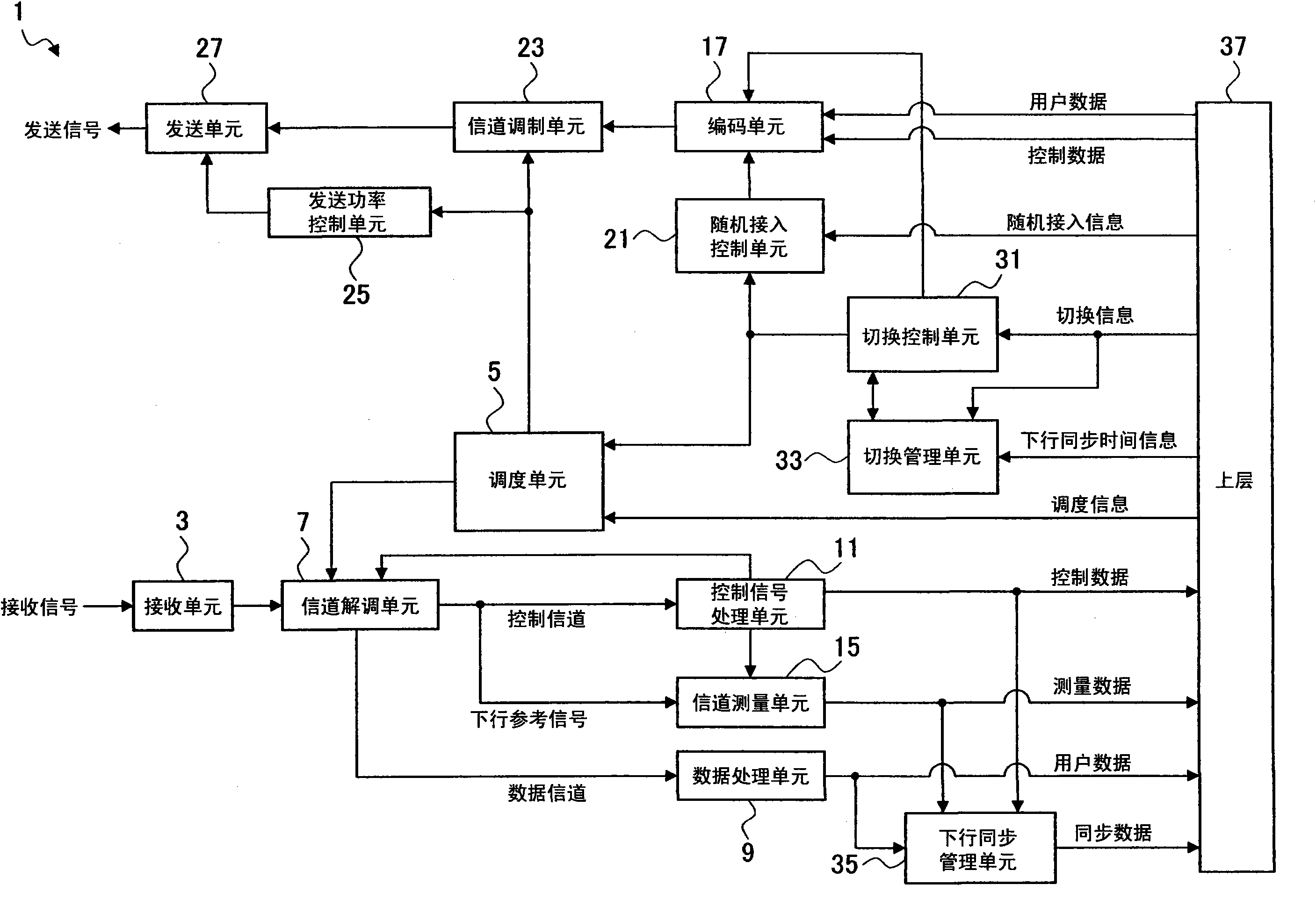
[0086] Hereinafter, Example 1 of the present invention will be described with reference to the drawings. figure 2 It is a functional block diagram showing a configuration example of a mobile station device according to Example 1 of the present invention. The mobile station device 1 according to this example includes: a receiving unit 3, a scheduling unit 5, a channel demodulation unit 7, a data processing unit 9, a control signal processing unit 11, a channel measurement unit 15, an encoding unit 17, and a random access control unit 21 , The channel modulation unit 23, the transmission power control unit 25, the transmission unit 27, the handover control unit 31, the handover management unit 33, the downlink synchronization management unit 35, and the upper layer 37.

[0087] The receiving unit 3 receives a received signal (a transmission signal from a base station device). The received signal is sent to the channel demodulation unit 7, demodulated based on the scheduling inform...

example 2

[0113] Next, a communication technique according to Example 2 of the present invention will be described with reference to the drawings. The characteristic of the communication technology according to this example is that in addition to the downlink synchronization establishment time, the effective time of the uplink synchronization is also considered.

[0114] Picture 9 It is a functional block diagram of a configuration example of a mobile station device related to the communication technology according to Example 2 of the present invention. Picture 9 The mobile station device 10 shown in figure 2 The same configuration, and the only difference is that the uplink synchronization timer information L1 is input to the handover management unit 133. The uplink synchronization timer information L1 is time information indicating the effective time for maintaining the uplink transmission timing of the mobile station device based on the uplink synchronization information notified by t...

example 3

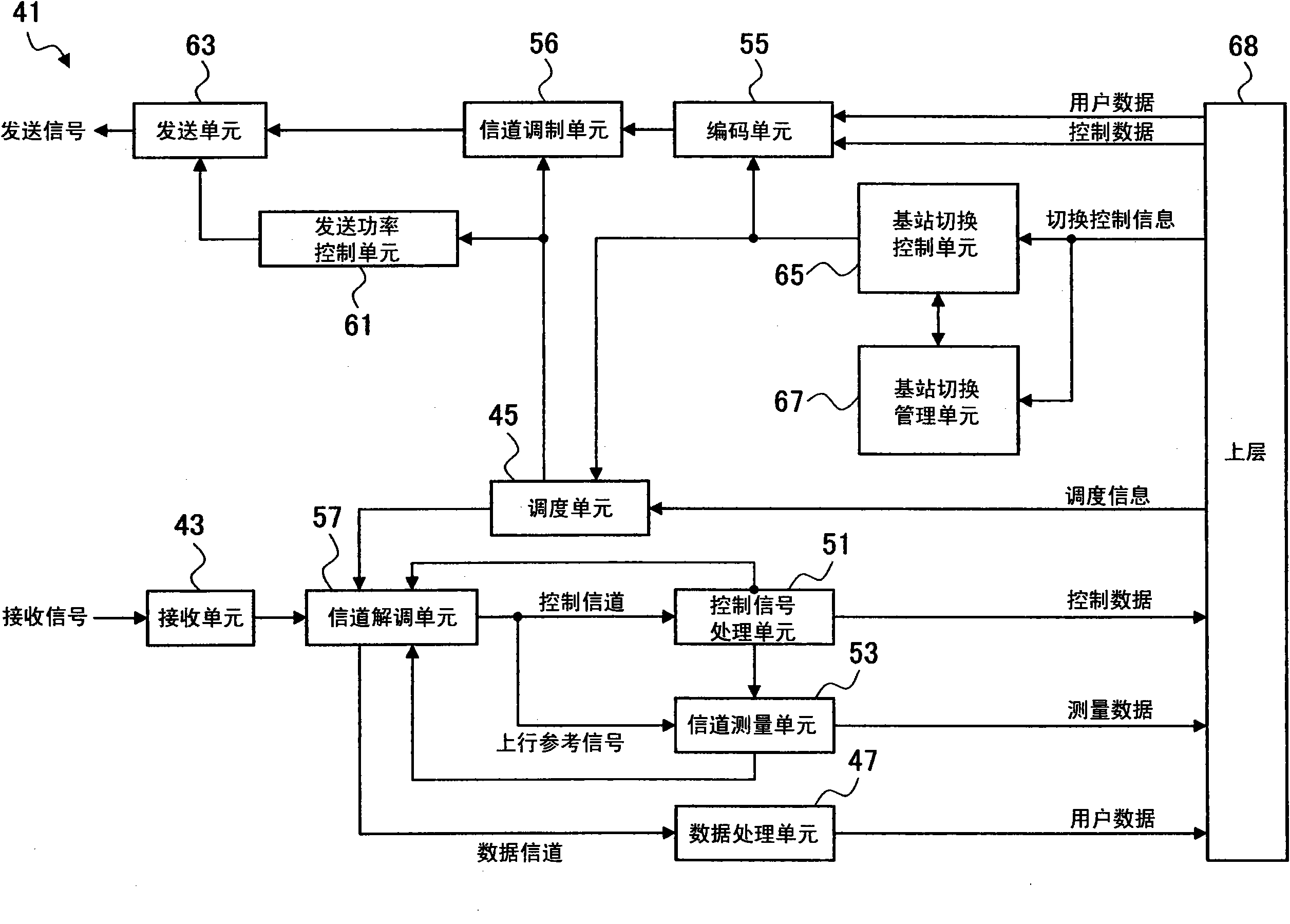
[0136] Next, a communication device according to Example 3 of the present invention will be described with reference to the drawings. The communication technology according to this example shows an example in which the handover instruction message is received later than the handover execution time.

[0137] Figure 18 It is a functional block diagram showing a configuration example of a mobile station device related to the communication technology according to Example 3 of the present invention. Figure 18 The mobile station device 20 shown has the Picture 9 With the same configuration, the only difference is that the upper layer 37 inputs the switching instruction message reception time information L2 to the switching management unit 233. For other configuration blocks, use and Picture 9 The same reference number, and the description will not be repeated. The handover instruction message reception time information L2 is time information indicating the frame or subframe number ...


PUM


Abstract

A mobile station device acquires handover information when receiving a handover command message and continues a reception process in a source cell until a handover start time when it is judged that the command is for a synchronous handover. When the handover start time comes, a cell switching control is performed according to the handover information and a downward synchronization establishing process is started to the target cell. When the downward synchronization is established before an end of a handover protection time and it is judged that the synchronization establishment is completed within an expected downward synchronization establishment time through the judgment, it is judged that an upward synchronization establishment is not necessary to the target cell and the synchronous handover process in which a random access is not needed is performed. On the other hand, when it is judged that the synchronization establishment is not completed, it is judged that the upward synchronization establishment is necessary to the target cell and the handover process in which a random access transmission is needed is performed.

Description

Technical field [0001] The present invention relates to mobile communication technology, in particular to a handover control technology in mobile communication. Background technique [0002] Currently, the standards organization 3GPP (Third Generation Partnership Project, see Non-Patent Document 1 below) is studying the evolved universal terrestrial radio access (hereinafter referred to as "EUTRA"). EUTRA aims to improve communication speed by implementing some of the technologies studied for the fourth generation in the third generation frequency band. [0003] In EUTRA, it is determined that OFDMA (Orthogonal Frequency Division Multiplexing Access), which is resistant to multipath interference and suitable for high-speed transmission, is implemented as a communication system. As for the detailed specifications related to upper-layer operations (such as data transmission control and resource management control related to EUTRA), implement technologies that realize low-delay, low-...

Claims


Application Information

Patent Timeline
Patent Type & Authority Applications(China)
IPC IPC(8): H04W36/08H04W74/08
CPCH04W74/02H04W36/0055H04W36/0077
Inventor 上村克成
Owner SHARP KK
Why Eureka
Try Eureka