Trajectory determination method for non-productive movements

A technology of production time and track, applied in general control systems, instruments, computer control, etc., can solve problems such as high computing power, achieve low computing performance, reliable operation, and save time

Active Publication Date: 2018-03-27
SIEMENS AG
View PDF7 Cites 2 Cited by
  • Summary
  • Abstract
  • Description
  • Claims
  • Application Information

AI Technical Summary

Problems solved by technology

[0003] A disadvantage of the known machine control methods is that they are based on a large number of data sets about the tool environment, the supply and processing of which require high computing power when operating the machine

Method used


Image

  • Trajectory determination method for non-productive movements
  • Trajectory determination method for non-productive movements
  • Trajectory determination method for non-productive movements

Examples


Embodiment Construction

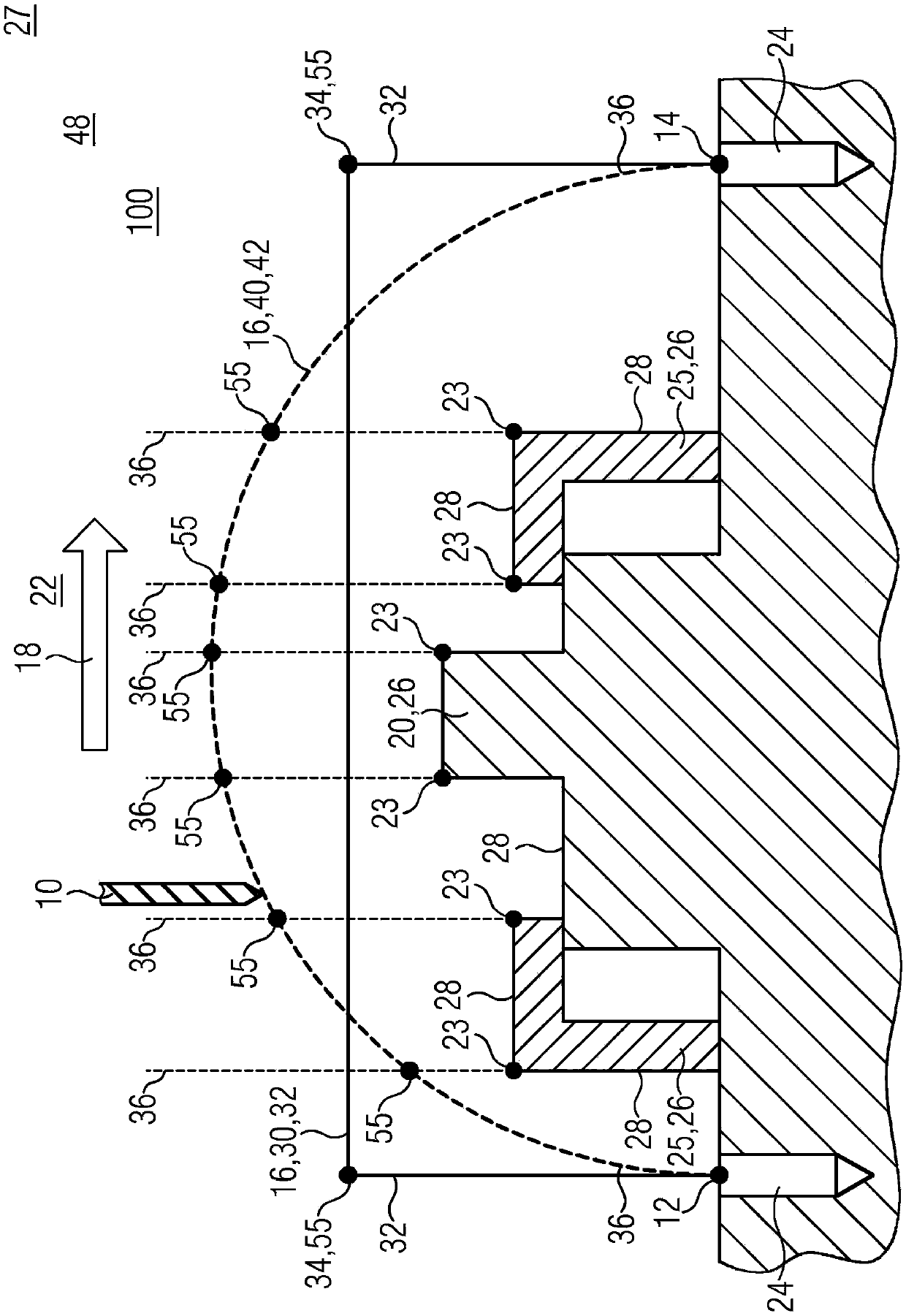
[0024] exist figure 1, shows a movement range 22 in which the tool 10 executes non-productive time movements 16 according to the method 100 according to the invention. The illustrated embodiment is used to execute non-productive movements of tool 10 in machine tool 50 . figure 1 Overall, the two-dimensional projection of the three-dimensional movement in the movement area 22 is shown. In the movement area 22 , besides the tool 10 , a workpiece 20 and a gripper 25 are arranged, which in each case represent an obstacle 26 for the tool 10 . exist figure 1 The further fixing of the clamp 25 is not shown in detail. The individual obstacles 26 each have a plurality of outer faces, which overall form a continuous obstacle contour 28 in the region of the workpiece 20 . The workpiece 20 , the holder 25 and the recess 24 have edges 23 on their surfaces which are relevant for the obstacle contour 28 to be considered. Information about the position of the workpiece 20, of the gripper...


PUM


Abstract

The invention relates to a trajectory determination method for non-productive movements of machine tools, and relates to a storage medium suitable for the method and a control unit used for the machine tools.

Description

technical field [0001] The invention relates to a method for determining a trajectory for a non-production-time movement of a machine tool, as well as to a program suitable therefor and an associated control unit for the machine tool. Background technique [0002] A method for machine tool control is known from DE 103 43 611 A1, in which the workspace is divided into discrete elements. For each discrete element, a binary collision parameter for the tool is provided. If the tool moves past discrete elements while in motion, a collision hazard is identified based on a displayed lookup table. In addition, the tools themselves are represented by discretized models. [0003] A disadvantage of the known machine control methods is that they are based on a large number of data sets about the environment of the tool, the supply and processing of which require high computing power when operating the machine. Furthermore, according to the prior art, this method is based on the fact ...

Claims


Application Information

Patent Timeline
Patent Type & Authority Applications(China)
IPC IPC(8): G05B19/4061B25J9/16
CPCB25J9/1666G05B19/4061G05B2219/39361G05B2219/40476
Inventor 约亨·布雷特施奈德哈特穆特·林克
Owner SIEMENS AG
Why Eureka
Try Eureka