Automatic timing ball recovering device

An automatic and oil recovery technology, applied in the direction of cleaning hollow objects, cleaning methods and utensils, chemical instruments and methods, etc. Reliability, lower maintenance costs, and excellent anti-theft oil performance

Pending Publication Date: 2018-03-30
XIAN SHAN CHUAN PETROLEUM TECH CO LTD
View PDF8 Cites 0 Cited by
  • Summary
  • Abstract
  • Description
  • Claims
  • Application Information

AI Technical Summary

Problems solved by technology

However, most of the ball collecting devices in the prior art have problems such as ball pinching, ball jamming, poor throwing effect and efficiency for wax removal balls of different specifications, and cannot be automatically cleaned by setting, wasting a lot of manpower and material resources

Method used


Image

  • Automatic timing ball recovering device
  • Automatic timing ball recovering device
  • Automatic timing ball recovering device

Examples


Embodiment 1

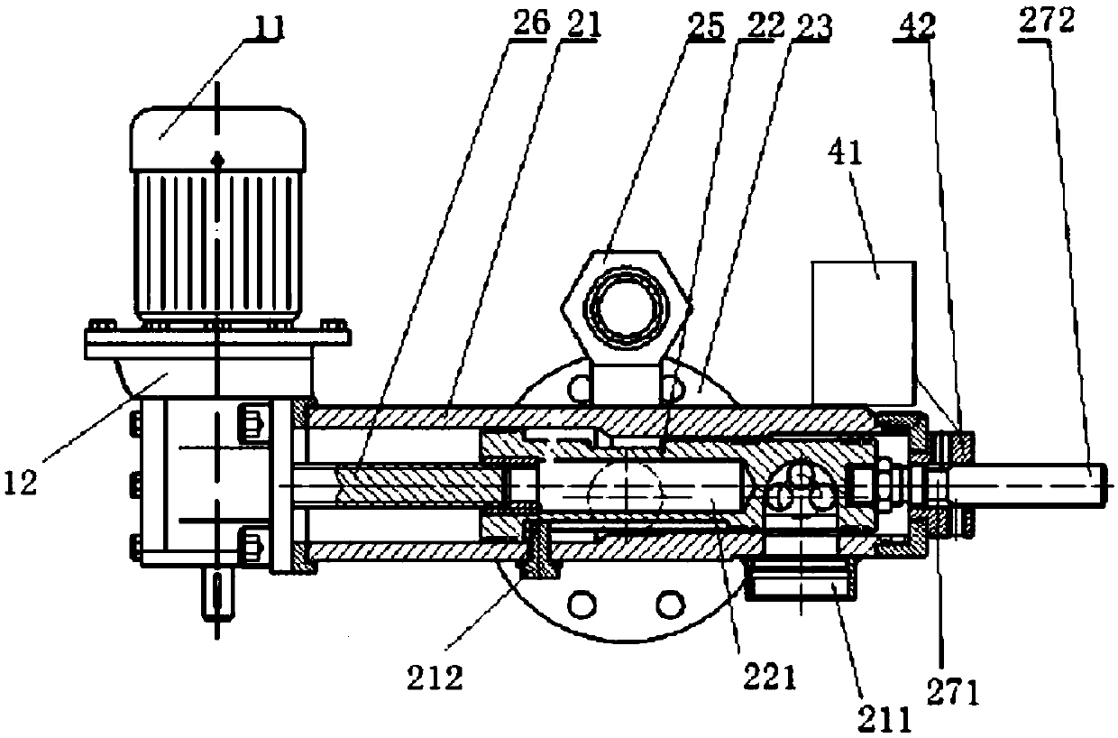
[0026] Such as image 3 As shown, in this embodiment, the travel switch 27 is composed of a connecting rod 271, a U-shaped induction switch 272 and an anti-loosening nut; one end of the connecting rod 271 is provided with an external thread, which is threaded through the anti-loosening nut and the plunger 22 , and the other end is fixedly connected with the U-shaped inductive switch 272, and the U-shaped inductive switch 272 is in point contact with the limit sensor 42.

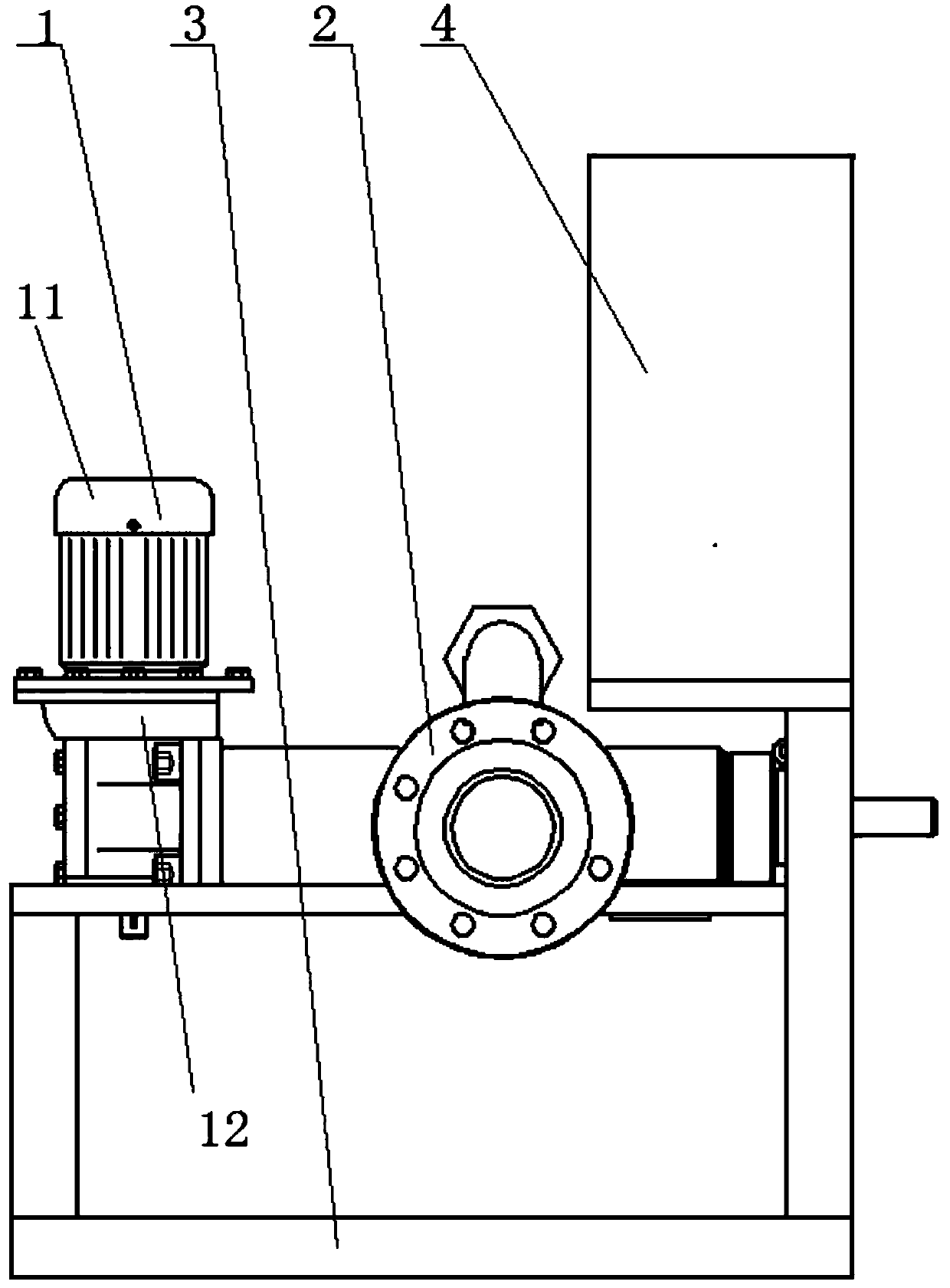
[0027] When in use, the user sets the time and duration for the device to be turned on in the PLC controller 41. When the set time is reached, the PLC controller 41 controls the motor 11 to turn on, the motor 11 drives the reducer 12 to rotate, and the reducer 12 drives the screw rod 26 to rotate. , the plunger 22 is cylindrical to ensure that it will not rotate when moving; the plunger 22 screwed with the screw rod 26 starts to move to the left in the body 21, and the ball-taking groove 221 on the plunger 22...

Embodiment 2

[0031] Such as image 3 As shown, in this embodiment, the travel switch 27 is composed of a connecting rod 271, a U-shaped induction switch 272 and an anti-loosening nut; one end of the connecting rod 271 is provided with an external thread, which is threaded through the anti-loosening nut and the plunger 22 , and the other end is fixedly connected with the U-shaped inductive switch 272, and the U-shaped inductive switch 272 is in point contact with the limit sensor 42.

[0032] When in use, the user sets the time and duration for the device to be turned on in the PLC controller 41. When the set time is reached, the PLC controller 41 controls the motor 11 to turn on, the motor 11 drives the reducer 12 to rotate, and the reducer 12 drives the screw rod 26 to rotate. , the plunger 22 is cylindrical to ensure that it will not rotate when moving; the plunger 22 screwed with the screw rod 26 starts to move to the left in the body 21, and the ball-taking groove 221 on the plunger 22...

Embodiment 3

[0036] Such as image 3 As shown, as a preferred implementation of the above embodiment, in this embodiment, the travel switch 27 includes a connecting rod 271, a U-shaped induction switch 272 and an anti-loosening nut; the anti-loosening nut at one end of the connecting rod 271 passes through the connecting rod The connecting rod 271 and the U-shaped sensor switch 272 are screwed to the plunger 22 by the screw thread on the upper body. The connecting rod 271 passes through the body 21 and contacts with the limit sensor 42 installed on the body 21. The connecting rod 271 is in addition One end is fixedly connected with a U-shaped inductive switch 272 , and the U-shaped inductive switch 272 is in electrical contact with the limit sensor 42 .

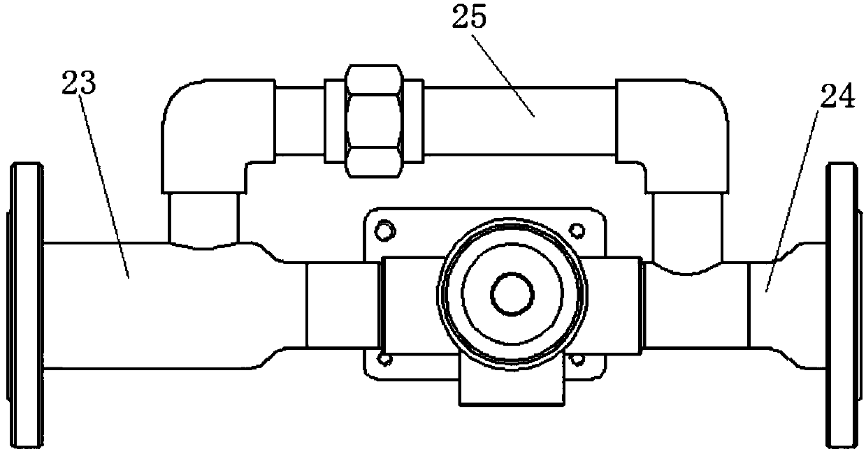
[0037] The ball-taking groove 221 is L-shaped, the inlet is at the same height as the flange nipple 23, and the outlet is at the same level as the ball outlet 211.

[0038] When in use, the user sets the time and duration for the device ...


PUM


Abstract

The invention discloses an automatic timing ball recovering device, which comprises a base (3) and a power mechanism (1). An execution mechanism (2) comprises a hollow-structured body (21) with an opening in one end, a plunger (22) which is slidably arranged in the body (21) and provided with a threaded groove in the middle in a concave way, an inlet flange pup joint (23) communicating with a sideface of the body (21), an outlet flange pup joint (24) directly facing the inlet flange pup joint (23) and commutating with the body (21), a distributing pipeline (25) provided with the pipe diameterbeing smaller than the flange pup joints (23, 24) and communicating with the inlet flange pup joint (23) and the outlet flange pup joint (24), and a screw rod (26). The automatic timing ball recovering device provided by the invention can be used for automatically recovering balls of paraffin and oil sludge in a clearing pipeline according to the setting of a user, solves the problems of ball clamping and stucking existed in an oil field system ball recovering device, poor feeding effect and efficiency of paraffin removal balls with different specifications, and the like in the prior art, andis reliable and safe to work, and beneficial for reducing maintenance cost.

Description

technical field [0001] The invention belongs to the field of oil pipeline cleaning, in particular to a timing automatic ball collection device. Background technique [0002] At present, the petroleum crude oil produced in our country contains paraffin to varying degrees. Crude oil will precipitate paraffin to varying degrees during pipeline transportation. Paraffin sticks to the wall of the crude oil delivery pipe, seriously affecting the flow rate of crude oil and normal oil delivery. [0003] Therefore, the ball-throwing device has appeared, which can remove wax, sludge, etc., and recycle simultaneously, and the corresponding ball-collecting device has also arisen at the historic moment. However, most of the ball collecting devices in the prior art have problems such as ball pinching, ball jamming, poor throwing effect and efficiency for wax removal balls of different specifications, and cannot be automatically cleaned by setting, wasting a lot of manpower and material r...

Claims


Application Information

Patent Timeline
Patent Type & Authority Applications(China)
IPC IPC(8): B08B9/055
CPCB08B9/0552
Inventor 潘年明王海飞王萌杨威
Owner XIAN SHAN CHUAN PETROLEUM TECH CO LTD
Why Eureka
Try Eureka