
A centrifugal casting machine

A technology of centrifugal casting machine and centrifuge, which is applied in the field of casting, can solve the problems of insufficient density of pipe fittings, achieve the effect of improving molding purity, increasing success rate, and eliminating vibration problems

Active Publication Date: 2020-04-14
重庆麦纳昇科技有限公司
View PDF4 Cites 0 Cited by
  • Summary
  • Abstract
  • Description
  • Claims
  • Application Information

AI Technical Summary

Problems solved by technology

[0003] The present invention aims at the above-mentioned existing technical problems, and provides a centrifugal casting machine to solve the problem of insufficient density of pipe fittings currently used in vertical centrifugal casting machines

Method used


Image

  • A centrifugal casting machine

Examples


Embodiment Construction

[0014] Further detailed explanation through specific implementation mode below:

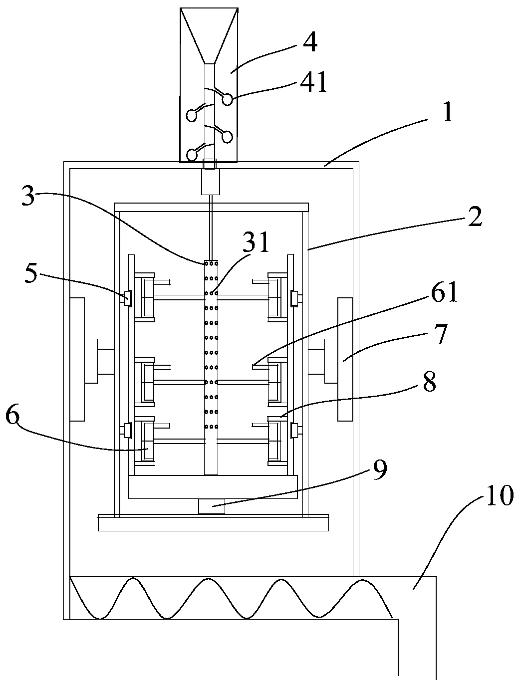
[0015] The reference signs in the accompanying drawings list: shell 1, rotating barrel 2, sprue column 3, warming pipe 31, filter 4, filter residue ball 41, guide wheel 5, ceramic mold 6, ceramic tube 61, telescopic hydraulic cylinder 7 , electromagnetic generator 8, high-speed motor 9, sand-discharging mechanism 10.

[0016] Such as figure 1 The centrifugal casting machine shown includes a casing 1, and a vertically placed centrifuge is arranged inside the casing 1. The centrifuge includes a base, a rotating barrel 2, and a high-speed motor 9 is installed at the center of the bottom of the rotating barrel 2, and the rotation center of the rotating barrel 2 is set There is a mold mounting seat, and the pouring device is fixedly installed on the mold mounting seat. The pouring device includes a sprue column 3 in the center of the rotating barrel 2, and a sprue filter 4 is connected to the top of ...


PUM


Abstract

The scheme discloses a centrifugal casting machine in the field of casting. The centrifugal casting machine comprises a shell, wherein a vertically-placed centrifuge is arranged in the shell; the centrifuge comprises a base and a rotating barrel; the outer side of the bottom of the rotating barrel is provided with a high-speed motor; the inner side of the center of the bottom of the rotating barrel is provided with a mold mounting seat; a casting device is fixedly arranged on the mold mounting seat and comprises a pouring gate column fixed on the mold mounting seat; the side wall of the pouring gate column communicates with ceramic molds; the rotating barrel is filled with cooling sand; the outer wall of the rotating barrel is provided with a stabilizing device which comprises a stabilizing rack; the outer wall of the stabilizing rack is provided with guide wheels; the outer wall of the rotating barrel is provided with a guide wheel rail matched with the guide wheels; the rail is as high as the ceramic molds; and the upper end of each ceramic mold communicates with a ceramic pipe filled with eroding materials. By adopting the centrifugal casting machine, the yield of castings can be effectively improved.

Description

technical field [0001] The invention relates to the field of casting, in particular to a centrifugal casting machine. Background technique [0002] Centrifugal casting machine is a machine that pours liquid solution into a rotating mold, completes filling and solidification molding under the action of centrifugal force to obtain metal castings; the centrifugal casting machine commonly used now is horizontal centrifugal casting machine, horizontal centrifugal casting machine The casting machine places the forming mold horizontally and adopts high-speed rotation in the vertical direction to form the pipe fittings. Now the centrifugal rotation power is mainly provided by the friction between the outer wall of the centrifugal barrel and the tugboat, which is a line contact, and the line contact area is relatively small. The friction force provided is relatively small, so that the speed of the horizontal centrifugal movement cannot meet the requirements of manufacturing large pip...

Claims


Application Information

Patent Timeline
Patent Type & Authority Patents(China)
IPC IPC(8): B22D13/02B22D13/10
CPCB22D13/026B22D13/107
Inventor 樊明
Owner 重庆麦纳昇科技有限公司
Learn More