Dam trash rack solid trash removing device

A technology for cleaning devices and trash racks, applied in water conservancy projects, artificial waterways, buildings, etc., can solve the problems of high maintenance costs, dirty cleaning, and jammed rakes, so as to reduce procurement and use costs, improve Stable and reliable performance, avoiding derailment and stuck effects

Pending Publication Date: 2018-03-30
戴娇
View PDF7 Cites 6 Cited by
  • Summary
  • Abstract
  • Description
  • Claims
  • Application Information

AI Technical Summary

Problems solved by technology

However, because the upper and lower edges of the rake-type cleaning machine are prone to deviation due to changes in water flow and solid dirt blocking, the overall tilt of the rake will cause the up and down operation to be unstable, or even stuck, which seriously causes the steel cable to pull In order to prevent the above situation from happening, the method of increasing the working gap is often adopted. However, as the gap increases, the tooth rake will swing from side to side, which will easily lead to unclean cleaning of the dirt between the bars and even the guide on both sides of the tooth rake. The derailment of the wheel and the steel cable will cause the rake to be stuck or the steel cable will be severely worn, which will affect the working status and service life of the cleaning machine; It will not be made t

Method used


Image

  • Dam trash rack solid trash removing device
  • Dam trash rack solid trash removing device
  • Dam trash rack solid trash removing device

Examples


Embodiment Construction

[0020] The present invention will be further described below in conjunction with the accompanying drawings and examples, but the present invention is not limited in any way. Any changes or improvements made based on the teaching of the present invention belong to the protection scope of the present invention.

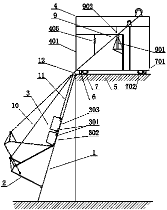
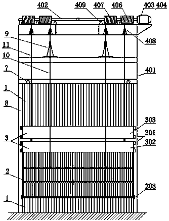
[0021] Such as Figures 1 to 5 As shown, the present invention includes a cleaning rake 2 arranged on the water inlet side of the trash rack 1, a counterweight truck 3 that is arranged above the trash rack 2 and hinged thereto, and is arranged on the top of the trash rack 1 and is used to drive the The traction mechanism 4 for the up and down movement of the heavy vehicle 3 and the turning of the cleaning rake 2, the base 5 fixed on the top of the cleaning grid 1 and the track 6 parallel to the cleaning grid 1, fixed at the bottom of the traction mechanism 4 and connected to the track 6. Rolling and cooperating walking mechanism 7, the counterweight truck 3 rolls and co...


PUM


Abstract

The invention discloses a dam trash rack solid trash removing device. The dam trash rack solid trash removing device comprises a trash removing rake arranged on the water inlet side of a trash rack, acounterweight car arranged above the trash rack in a hinged mode, a traction mechanism for driving the counterweight car to move and turning over the trash removing rake, a base fixedly arranged above the trash rack, rails parallel to the trash rack, and a traveling mechanism which is arranged at the bottom of the traction mechanism and matched with the rails; the counterweight car is in rollingfit with guide rails arranged on the two sides of the trash rack, or with rack strips through guide wheels on the two sides; the trash removing rake inversely covers the trash rack in a C shape, the upper portion of the trash removing rake is hinged to the counterweight car, the lower middle portion of the trash removing rake is connected with a rack turning cable of the traction mechanism, and the trash removing rake is provided with rack teeth inserted into the trash rack; and the traction mechanism comprises a machine frame of which the bottom is fixedly provided with the traveling mechanism, and a spindle arranged on the upper portion of the machine frame, the spindle connected with an output shaft of a speed reducer driven by a motor and wound with a lifting cable and the rake turningcable, the lifting cable is connected with the counterweight car, and the machine frame is provided with a hydraulic rake turning mechanism for enabling the rake turning cable to go up and down. Thedam trash rack solid trash removing device has the characteristics of being simple in structure, stable and reliable in work and high in slag removing efficiency.

Description

technical field [0001] The invention belongs to the technical field of water conservancy equipment, and in particular relates to a dam trash rack solid waste cleaning device with simple structure, stable and reliable operation, high slag cleaning efficiency, energy saving and consumption reduction. Background technique [0002] Energy is the material basis of human activities. In today's world, the development of energy, energy and the environment is a common concern of the whole world and all mankind, and it is also an important issue of my country's social and economic development. As people pay more and more attention to the environment, clean energy has developed rapidly. As a renewable energy source in nature, water energy is repeatedly regenerated along with the hydrological cycle, and one of the main forms of water energy utilization is hydropower generation. In the process of converting water energy into electric energy, hydropower does not undergo chemical changes...

Claims


Application Information

Patent Timeline
IPC IPC(8): E02B5/08
CPCE02B5/085
Inventor 戴娇
Owner 戴娇
Why Eureka
Try Eureka