P-gear parking mechanism and car
A parking mechanism and parking technology, applied to mechanical equipment, components with teeth, belts/chains/gears, etc., can solve the problems of large housing space, danger, scattered parts, etc., and achieve reliable structure High performance, prevent accidental shifting, and good stability
- Summary
- Abstract
- Description
- Claims
- Application Information
AI Technical Summary
Problems solved by technology
Method used
Image
Examples
Embodiment 1
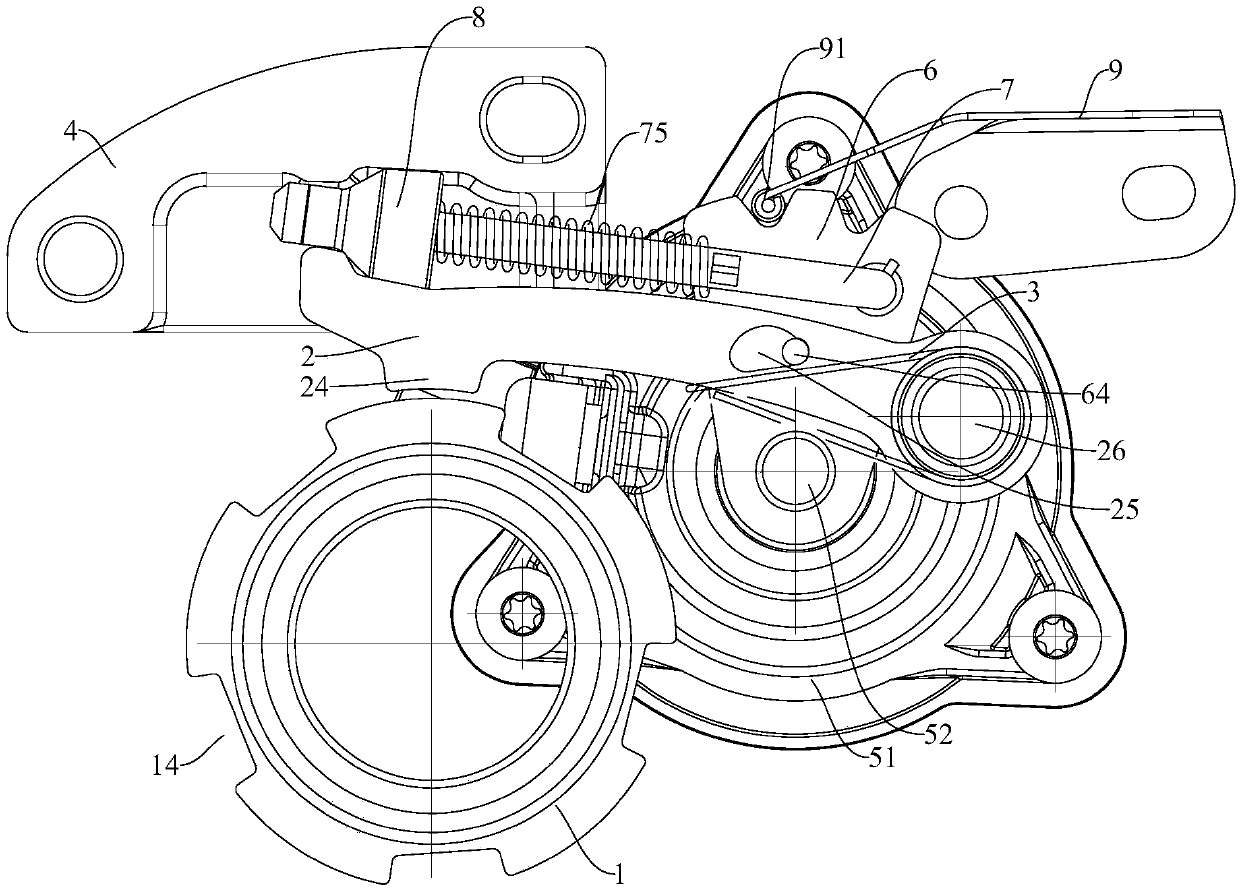
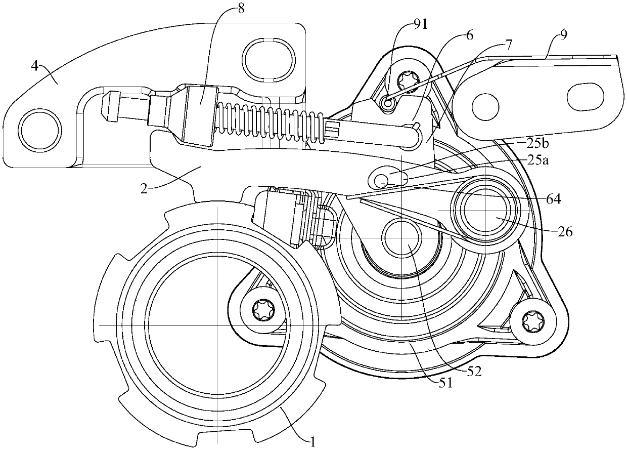
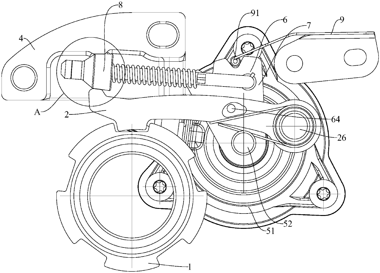
[0046] Such as Figure 1-Figure 3 As shown, the P-speed parking mechanism according to an embodiment of the present invention includes: a housing (not shown in the figure), a parking gear 1, a pawl 2, a stop block 4, an actuator 51 and a pull rod assembly.
[0047] Among them, the housing can be connected to the reducer case, and the parking gear 1 can be connected to the driving force assembly of the vehicle. For example, the parking gear 1 can be fixedly connected to the main reducer gear, and the parking gear 1 can have a locking groove. 14. When the parking gear 1 is locked, the power output can be cut off to realize P-speed parking.
[0048] The pawl 2 is pivotally installed in the housing, the pawl 2 can be pivotally mounted to the housing through a pawl pivot shaft 26, the pawl pivot shaft 26 can be fixedly connected to the housing, and the pawl 2 passes through a through-hole sleeve. Located outside the pawl pivot shaft 26 and in clearance fit with the pawl pivot shaft 26, ...
Embodiment 2
[0057] Such as Figure 1-Figure 3 As shown, the P-speed parking mechanism according to an embodiment of the present invention includes: a housing (not shown in the figure), a parking gear 1, a pawl 2, a stop block 4, an actuator 51 and a pull rod assembly.
[0058] Among them, the housing can be connected to the reducer case, and the parking gear 1 can be connected to the driving force assembly of the vehicle. For example, the parking gear 1 can be fixedly connected to the main reducer gear, when the parking gear 1 is locked , You can cut off the power output.
[0059] The pawl 2 is pivotally installed in the housing, the pawl 2 can be pivotally mounted to the housing through a pawl pivot shaft 26, the pawl pivot shaft 26 can be fixedly connected to the housing, and the pawl 2 passes through a through-hole sleeve. It is arranged outside the pawl pivot shaft 26, and the pawl 2 is in clearance fit with the pawl pivot shaft 26, the pawl 2 may be a long plate shape.
[0060] The pawl 2 ...
Embodiment 3
[0069] Such as Figure 1-Figure 3 As shown, the P-speed parking mechanism according to an embodiment of the present invention includes: a housing (not shown in the figure), a parking gear 1, a pawl 2, a stop block 4, an actuator 51 and a pull rod assembly.
[0070] Among them, the housing can be connected to the reducer case, and the parking gear 1 can be connected to the driving force assembly of the vehicle. For example, the parking gear 1 can be fixedly connected to the main reducer gear, when the parking gear 1 is locked , You can cut off the power output.
[0071] The pawl 2 is pivotally installed in the housing, the pawl 2 can be pivotally mounted to the housing through a pawl pivot shaft 26, the pawl pivot shaft 26 can be fixedly connected to the housing, and the pawl 2 passes through a through-hole sleeve. It is arranged outside the pawl pivot shaft 26, and the pawl 2 is in clearance fit with the pawl pivot shaft 26, the pawl 2 may be a long plate shape.
[0072] The pawl 2 ...
PUM
| Property | Measurement | Unit |
|---|---|---|
| Angle | aaaaa | aaaaa |
Abstract
Description
Claims
Application Information
 - R&D
- Intellectual Property
- Life Sciences
- Materials
- Tech Scout
- Unparalleled Data Quality
- Higher Quality Content
- 60% Fewer Hallucinations
Browse by: Latest US Patents, China's latest patents, Technical Efficacy Thesaurus, Application Domain, Technology Topic, Popular Technical Reports.
© 2025 PatSnap. All rights reserved.Legal|Privacy policy|Modern Slavery Act Transparency Statement|Sitemap|About US| Contact US: help@patsnap.com


