Aluminum alloy smelting furnace and smelting device

A technology for smelting furnaces and aluminum alloys, which is applied in the direction of furnace control devices, furnaces, furnace components, etc., can solve the problems such as the greater influence of the suction device on the work, and achieve the effect of avoiding the influence

Pending Publication Date: 2018-03-30
重庆顺博铝合金股份有限公司
View PDF0 Cites 1 Cited by
  • Summary
  • Abstract
  • Description
  • Claims
  • Application Information

AI Technical Summary

Problems solved by technology

[0004] The object of the present invention is to provide an aluminum alloy smelting furnace to improve the existing aluminum melting furnace. In order to form a better seal, the cover and the furnace body are usually screwed. This method has an impact on the work of the suction device. bigger problem
[0005] The purpose of the present invention is to provide a smelting device to improve the existing aluminum melting furnace. In order to form a better seal, the cover and the furnace body are usually screwed together, which has a great impact on the work of the suction device. The problem

Method used


Image

  • Aluminum alloy smelting furnace and smelting device
  • Aluminum alloy smelting furnace and smelting device
  • Aluminum alloy smelting furnace and smelting device

Examples


Embodiment 1

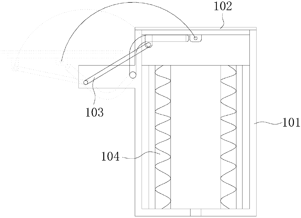
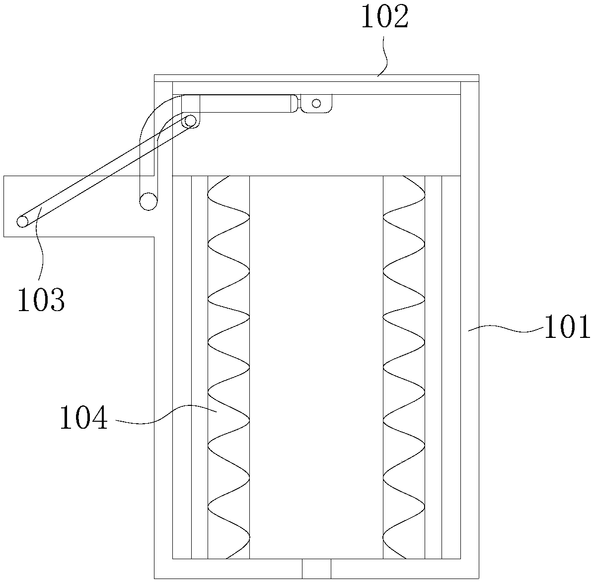
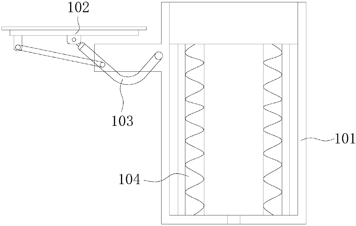
[0053] refer to Figure 1 to Figure 7 , the present embodiment provides an aluminum alloy melting furnace, including a furnace body 101, a cover body 102, a control device 103 and a melting device 104, the cover body 102 is connected with the furnace body 101 through the control device 103, and the control device 103 makes the cover body 102 Move relative to the furnace body 101 in a translational manner, the cover body 102 and the furnace body 101 form a furnace 105, the end of the furnace body 101 away from the cover body 102 is provided with an outlet 106, the outlet 106 communicates with the furnace chamber 105, and the melting device 104 is located in the furnace chamber 105 Inside, the smelting device 104 includes a high-frequency heating device 107, a heat collecting device 108, and a reflective layer 109 arranged in sequence. The reflective layer 109 is connected to the furnace body 101, and the reflective layer 109 is located between the high-frequency heating device 1...

Embodiment 2

[0064] This embodiment provides a smelting device 104, including the aluminum alloy smelting furnace as above.

[0065] The smelting device 104 provided in this embodiment includes the above-mentioned aluminum alloy smelting furnace, which will not affect the operation of the suction device during operation.


PUM


Abstract

The invention provides an aluminum alloy smelting furnace and a smelting device and belongs to the technical field of metal smelting. The aluminum alloy smelting furnace comprises a furnace body, a cover body, a control device and the smelting device. The cover body is connected with the furnace body through the control device. The control device controls the cover body to move relative to the furnace body in a translational mode. The cover body and the furnace body constitute a furnace hearth. The end, far from the cover body, of the furnace body is provided with an outlet. The outlet communicates with the furnace hearth. The smelting device is located in the furnace hearth. The smelting device comprises a high-frequency heating device, a heat collection device and a reflecting layer which are arranged in sequence. The reflecting layer is connected with the furnace body. The reflecting layer is located between the high-frequency heating device and the furnace body. The smelting devicecomprises the aluminum alloy smelting furnace. The aluminum alloy smelting furnace provided by the invention is provided with the control device; the cover body and the furnace body can be opened andclosed just through translational motion so that the influence of opening and closing of a shell on a suction device can be effectively avoided.

Description

technical field [0001] The invention relates to the technical field of metal smelting, in particular to an aluminum alloy smelting furnace and a smelting device. Background technique [0002] The aluminum melting furnace is a new type of high-efficiency energy-saving furnace developed according to the aluminum smelting process. It can well meet the requirements of the aluminum smelting process: strict alloy composition requirements, discontinuous production, and large single furnace capacity. , Reduce burning loss, improve product quality, reduce labor intensity, improve working conditions and increase production efficiency. It is suitable for intermittent operations, smelting with a lot of alloys and recycled materials. [0003] The inventor found in the research that the existing aluminum melting furnace has at least the following disadvantages: in order to form a better seal in the existing aluminum melting furnace, screw connection is usually used between the lid and the...

Claims


Application Information

Patent Timeline
IPC IPC(8): F27D1/18F27D7/06F27D19/00
CPCF27D1/1808F27D7/06F27D19/00F27D2007/066F27D2019/0084F27D2001/1841
Inventor 王增潮李新生罗乐
Owner 重庆顺博铝合金股份有限公司
Why Eureka
Try Eureka