
Display panel and display device

A display panel and display area technology, which is applied to measurement devices, instruments, computing, etc., can solve problems such as the narrow frame and large width difference of the display panel, and achieve the advantages of saving manufacturing process, reducing width and improving manufacturing efficiency. Effect

Active Publication Date: 2018-03-30
SHANGHAI AVIC OPTOELECTRONICS
View PDF5 Cites 37 Cited by
  • Summary
  • Abstract
  • Description
  • Claims
  • Application Information

AI Technical Summary

Problems solved by technology

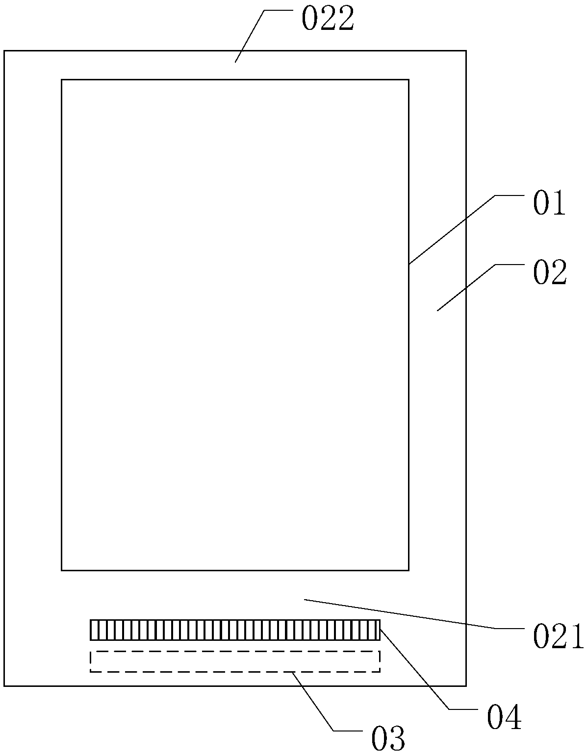
[0006] Since the lower frame area 021 is provided with the binding area 03, the test circuit 04 and other structures, the lower frame area 021 is much wider than the upper frame area 022, and the width difference between the lower frame area 021 and the upper frame area 022 is large, which is not conducive to realizing the display Narrow bezel of the panel,

Method used


Image

  • Display panel and display device
  • Display panel and display device
  • Display panel and display device

Examples


Embodiment Construction

[0030] Various exemplary embodiments of the present invention will now be described in detail with reference to the accompanying drawings. It should be noted that the relative arrangements of components and steps, numerical expressions and numerical values ​​set forth in these embodiments do not limit the scope of the present invention unless specifically stated otherwise.

[0031] The following description of at least one exemplary embodiment is merely illustrative in nature and in no way taken as limiting the invention, its application or uses.

[0032] Techniques, methods and devices known to those of ordinary skill in the relevant art may not be discussed in detail, but where appropriate, such techniques, methods and devices should be considered part of the description.

[0033] In all examples shown and discussed herein, any specific values ​​should be construed as exemplary only, and not as limitations. Therefore, other instances of the exemplary embodiment may have dif...


PUM


Abstract

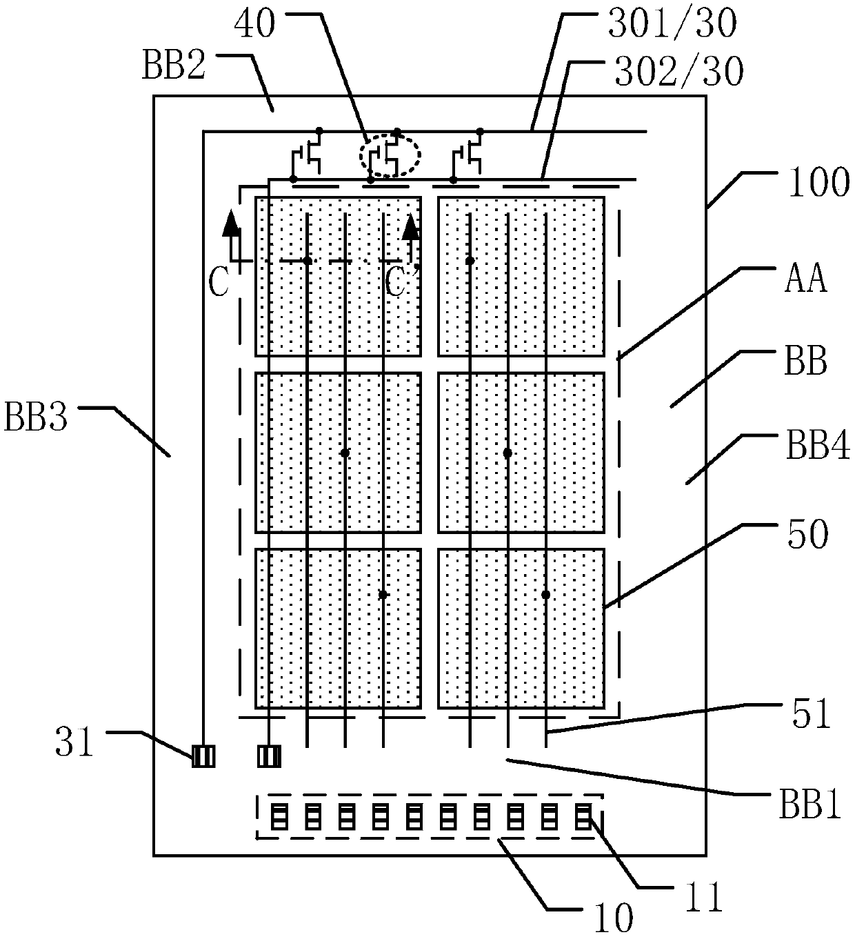
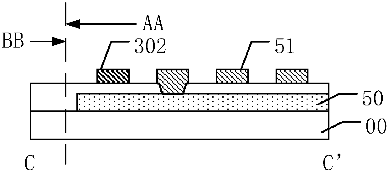
The invention discloses a display panel and a display device, and belongs to the technical field of display. The display panel includes a first substrate which includes a display area and a non-display area around the display area; the display area includes a plurality of first touch electrodes and a plurality of first touch electrode lines; the non-display area includes a first frame area and a second frame area, the first frame area includes a binding area, and the binding area includes a plurality of conductive bonding pads; the first substrate further includes a test circuit, and the testcircuit includes test wiring lines and a test transistor; the test transistor is disposed in the second frame area; one ends of the test wiring lines include signal input ends, and the signal input ends are disposed in the first frame area; at least one test wiring line extends from the second frame area, sequentially passes through the second frame area, the display area and the first frame area,and is disposed in the same layer as the first touch electrode lines. Compared with the prior art, the frame narrowing of the display panel is facilitated and the manufacturing efficiency of the display panel is improved.

Description

technical field [0001] The present invention relates to the field of display technology, and more particularly, to a display panel and a display device. Background technique [0002] With the development of display technology, display panels pursue narrower and narrower borders. [0003] Please refer to figure 1 , figure 1 It is a structural schematic diagram of a display panel provided by the prior art. figure 1 The shown display panel includes a display area 01 and a peripheral area 02. The display area 01 can display image information, and the peripheral area 02 can be provided with wiring, circuits, electronic components and other structures. [0004] The peripheral area 02 includes a lower frame area 021 and an upper frame area 022 , and the lower frame area 021 and the upper frame area 022 are located on opposite sides of the display area 01 . The lower border area 021 is provided with a binding area 03, and the binding area 03 is used for binding an IC chip or a f...

Claims


Application Information

Patent Timeline
IPC IPC(8): G06F3/041G01R31/26
CPCG01R31/26G01R31/2607G06F3/041G06F2203/04103
Inventor 秦丹丹曹兆铿夏志强王听海费日锂谢影秦锋刘金娥
Owner SHANGHAI AVIC OPTOELECTRONICS
Features
  • Generate Ideas
  • Intellectual Property
  • Life Sciences
  • Materials
  • Tech Scout
  • Unparalleled Data Quality
  • Higher Quality Content
  • 60% Fewer Hallucinations
Learn More