Backlight, production method thereof, backlight bottom frame and production method thereof

A manufacturing method and backlight technology, which are applied to the backlight bottom frame and its manufacture, backlight and its manufacturing field, can solve the problems of complex assembly process of the plastic frame 40 and the iron frame 50, increase the production cost of the liquid crystal display, etc., so as to save Complicated matching process, saving production cost, and the effect of reducing production cost

Active Publication Date: 2013-05-01
SHANGHAI TIANMA MICRO ELECTRONICS CO LTD
View PDF11 Cites 9 Cited by
  • Summary
  • Abstract
  • Description
  • Claims
  • Application Information

AI Technical Summary

Problems solved by technology

[0013] Additionally, when making figure 1 When the backlight is shown, it is necessary to make a plastic frame including a hook 41 and an iron frame including a slot 51, the hook 41 matches the slot 51, and the gap between the plastic frame 40 and the iron frame 50 90 should be as small as possible, so that the assembly process of the plastic frame 40 and the iron frame 50 is relatively complicated, which increases the production cost of the liquid crystal display

Method used


Image

  • Backlight, production method thereof, backlight bottom frame and production method thereof
  • Backlight, production method thereof, backlight bottom frame and production method thereof
  • Backlight, production method thereof, backlight bottom frame and production method thereof

Examples


Embodiment 1

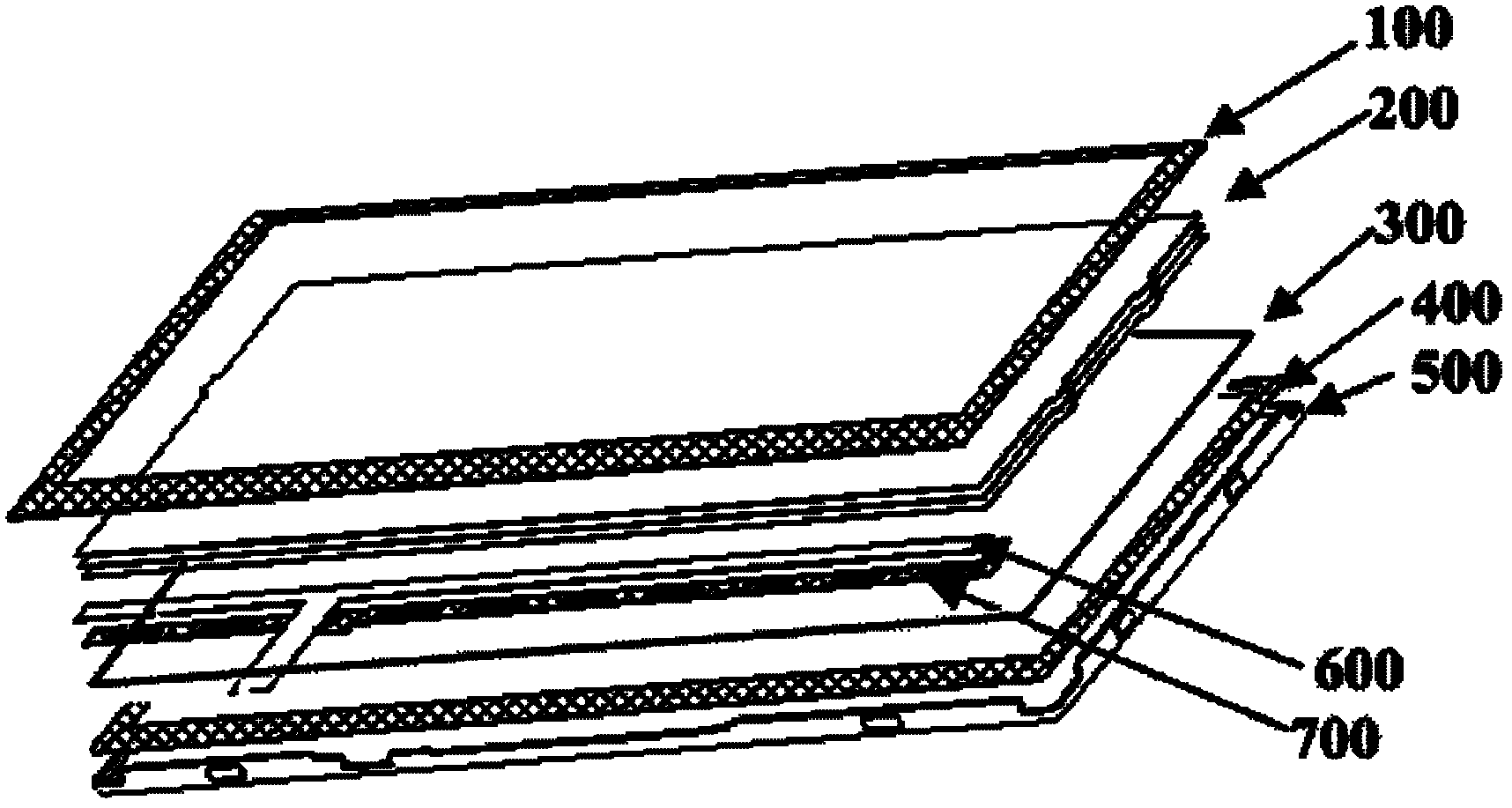
[0083] refer to image 3 As shown, this embodiment provides a backlight, including: an optical film 200, a light guide plate 300, a light source 600 and a bottom frame 500, wherein: the optical film 200 is arranged on the upper surface of the light guide plate 300, The light source 600 is arranged on the side of the light guide plate 300, and the lower surface of the light guide plate 300 is arranged on the bottom frame 500, and the bottom frame 500 includes a reflective layer (not shown in the figure) and a metal layer (not shown in the figure). shown), the reflective layer is adjacent to the light guide plate 300.

[0084] The bottom frame 500 in this embodiment includes a reflective layer and a metal layer, that is, the reflective sheet and the metal sheet in the prior art are combined into one, and the optical film 200 and the light source 600 are fixed on the light guide plate 300 , that is, the light guide plate 300 can replace the plastic frame to realize the function ...

Embodiment 2

[0101] This embodiment provides a liquid crystal display, with reference to Figure 4As shown, the liquid crystal display includes: an upper polarizer 820, a liquid crystal display panel 900 located on the lower surface of the upper polarizer 820, a lower polarizer 810 located on the lower surface of the liquid crystal display panel 900, and a lower polarizer located on the lower surface of the lower polarizer 820. The backlight source 111 on the lower surface of 810, the backlight source 111 includes a bottom frame, and the lower polarizer 810, the liquid crystal display panel 900 and the upper polarizer 820 are sequentially located in the bottom frame.

[0102] Wherein, the liquid crystal display panel 900 may include a color filter substrate and an array substrate oppositely arranged, and a liquid crystal layer located between the color filter substrate and the array substrate, which are well known to those skilled in the art, so I won't repeat them here.

[0103] Wherein,...

Embodiment 3

[0109] refer to Figure 6 As shown, this embodiment provides a method for manufacturing a backlight, including:

[0110] Step S1, providing a composite material, the composite material includes a reflective material and a metallic material, and the reflective material and the metallic material are laminated together;

[0111] Step S2, forming the composite material into a bottom frame, the bottom frame including a reflective layer formed of the reflective material and a metal layer formed of the metal material;

[0112] Step S3, providing a light guide plate, and disposing the lower surface of the light guide plate on the reflective layer;

[0113] Step S4, providing an optical film, and disposing the optical film on the upper surface of the light guide plate;

[0114] Step S5, providing a light source, and disposing the light source on the side or bottom of the light guide plate.

[0115] First, execute step S1, refer to Figure 7 As shown, a composite material is provide...


PUM

PropertyMeasurementUnit
thicknessaaaaaaaaaa
thicknessaaaaaaaaaa

Abstract

The invention relates to a backlight, a production method thereof, a backlight bottom frame and a production method thereof in the technical field of display. The backlight comprises an optical film, a light guide plate, a light source and the bottom frame, wherein the optical film is fixed on the top surface of the light guide plate, the light source is fixed on the side or bottom of the light guide plate, the bottom surface of the light guide plate is fixed on the bottom frame, the bottom frame comprises a reflective layer and a metal layer, and the reflective layer is in contact with the light guide plate. The production method of the backlight includes the following steps: composite materials, which are a reflective material and a metal material, are provided, and the reflective material and the metal material are stacked together; the composite materials are formed into the bottom frame, which comprises the reflective layer and the metal layer; the light guide plate is provided, and the bottom surface of the light guide plate is fixed on the reflective layer; the optical film is provided, and is placed on the top surface of the light guide plate; and the light source is provided, and is arranged on the side or bottom of the light guide plate. The frame of the backlight can be narrow, the production steps are simplified, and the production cost is reduced.

Description

technical field [0001] The invention relates to the field of display technology, in particular to a backlight source and a manufacturing method thereof, a backlight source bottom frame and a manufacturing method thereof. Background technique [0002] With the development of liquid crystal displays, liquid crystal displays are becoming more and more popular among consumers and widely used in various fields due to their advantages of thin thickness, small volume and small space occupation. Among them, in order to further save space, liquid crystal displays are increasingly required to have narrower borders. The liquid crystal display mainly includes: a backlight source and a liquid crystal display panel located on the backlight source. One of the determining factors of the frame width of the liquid crystal display is the distance between the edge of the liquid crystal display panel and the edge of the backlight source, that is, the frame width of the backlight source. [000...

Claims


Application Information

Patent Timeline
Patent Type & Authority Applications(China)
IPC IPC(8): F21S8/00F21V8/00F21V7/22F21V21/00G02F1/13357F21Y101/02
Inventor 李强
Owner SHANGHAI TIANMA MICRO ELECTRONICS CO LTD
Why Eureka
Try Eureka