Backlight module and display device

A backlight module and backplane technology, which is applied in the direction of lighting devices, fixed lighting devices, components of lighting devices, etc., can solve the problems of space occupied by positioning columns, movement of optical film materials, limited space of narrow frames, etc., and achieve reduction Border width, to achieve the effect of narrow border

Inactive Publication Date: 2014-08-27
BOE TECH GRP CO LTD +1
View PDF7 Cites 10 Cited by
  • Summary
  • Abstract
  • Description
  • Claims
  • Application Information

AI Technical Summary

Problems solved by technology

[0004] The first way, such as figure 1 As shown, the bending structure is processed on the back plate 10. The bent part of the back plate 10 is located between the sealant 30 and the light guide plate 50, and forms a positioning protrusion 10a (sheet guide). The edge is designed with a positioning hole 40a corresponding to the positioning protrusion 10a, which can facilitate the positioning and assembly of the optical film material 40 and the back plate 10, and can play a role in fixing the optical film material 40; but this structure Due to the processing of the bending structure on the backplane 10, it will be difficult to narrow the frame of the backlight module, so that it is also difficult to narrow the frame of the display product, and the space for narrowing the frame (frame slimming) of the backlight module is limited;
[0005] The second method is to make a separate circular positioning column on the back plate, and the edge of the optical film is designed with a U-shaped positioning gap that can be snapped into the circular positioning column; this structure is compared with the first method. With the back bending structure, although the frame can be narrowed to a certain extent, it is still necessary to reserve a certain space on the back panel to make the positioning column, that is, the positioning column will still occupy a certain space in the frame part, and the circular positioning column alone It is made on the back plate, and the production cost is high. In addition, the positioning of the circular positioning post and the U-shaped positioning notch also often causes poor movement of the optical film material.

Method used


Image

  • Backlight module and display device
  • Backlight module and display device

Examples


Embodiment Construction

[0024] The principles and features of the present invention are described below in conjunction with the accompanying drawings, and the examples given are only used to explain the present invention, and are not intended to limit the scope of the present invention.

[0025] Aiming at the problem that the positioning structure of the optical film material on the backplane of the traditional backlight module is not conducive to the narrow frame of the backlight module, the present invention provides a backlight module, which can effectively reduce the frame width of the backlight module , to realize the narrow border of display products.

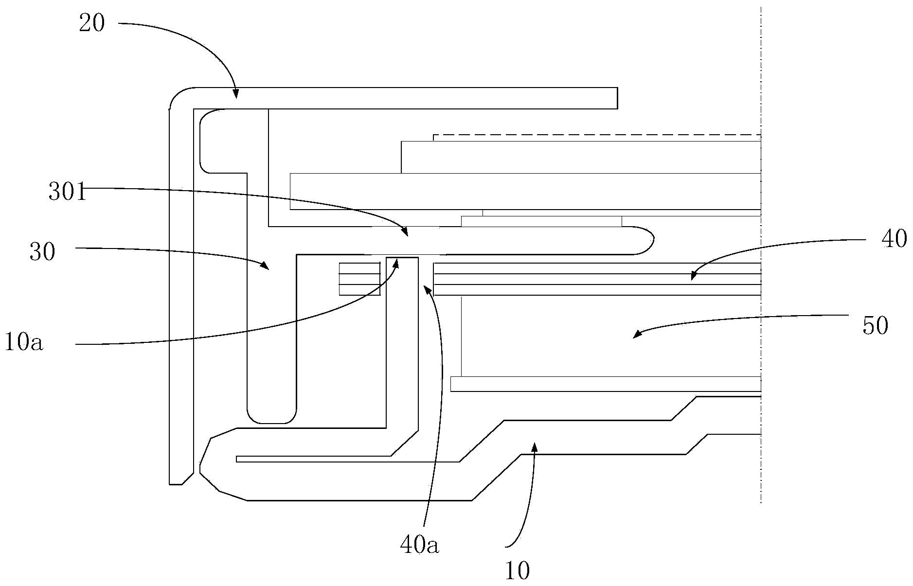
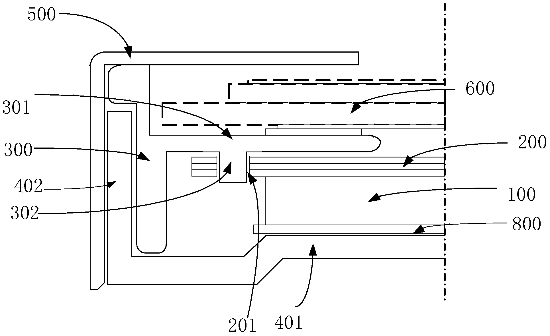
[0026] Such as figure 2 As shown, the backlight module provided by the present invention includes:

[0027] Light guide plate 100;

[0028] The optical film material 200 arranged on one side of the light guide plate 100, the edge position of the optical film material 200 is provided with a first positioning part 201;

[0029] The back plate ...


PUM


Abstract

The invention provides a backlight module and a display device. The backlight module comprises a light guide plate, an optical film material arranged on one side of the light guide plate and frame sealing glue arranged on the periphery of the light guide plate, wherein a first positioning part is arranged at the edge of the optical film material, the frame sealing glue comprises a covering part and a second positioning part, the covering part is located on one side, away from the light guide plate, of the optical film material, the edge of the optical film material is covered with the covering part, and the second positioning part is arranged on one face, towards the optical film material, of the covering part and matched with the first positioning part so as to positioning the optical film material. According to the backlight module, the positioning structures for positioning the optical film material are directly manufactured on the frame sealing glue, the width of a frame of the backlight module can be effectively reduced, and the frame of a displayed product can be narrow.

Description

technical field [0001] The invention relates to the field of display technology, in particular to a backlight module and a display device. Background technique [0002] Due to the advantages of low operating voltage, low power consumption, flexible display methods, and low radiation, Liquid Crystal Displays (LCDs) are widely used in various fields, such as computers, mobile phones, televisions, and measurement displays. The LCD includes a liquid crystal display panel, and the liquid crystal display panel includes a thin film transistor substrate, a color filter substrate, and a layer of liquid crystal molecules interposed between the two substrates. In addition, the LCD also includes a backlight module, which is used to provide a light source for the liquid crystal display panel, so that the LCD can display images. [0003] Such as figure 1 As shown, a traditional backlight module includes a back cover (Back Cover) 10, a frame (Bezel) 20, a sealant (Mold Frame) 30, an opti...

Claims


Application Information

Patent Timeline
Patent Type & Authority Applications(China)
IPC IPC(8): F21S8/00F21V17/10G02F1/13357
CPCG02F1/133308G02F1/133608G02B6/0081G02B6/0073
Inventor 周俊丽李友
Owner BOE TECH GRP CO LTD
Why Eureka
Try Eureka