Rapid wiring terminating mechanism

A terminal and termination technology, applied in the field of electrical conduction, can solve the problems of unfavorable promotion and application of electrical connectors, achieve the effects of shortening disassembly time, minimizing losses, and improving installation efficiency

Pending Publication Date: 2018-03-30
ZHEJIANG ZHONGHANG ELECTRONICS
View PDF0 Cites 6 Cited by
  • Summary
  • Abstract
  • Description
  • Claims
  • Application Information

AI Technical Summary

Problems solved by technology

The socket is fixed on the electrical parts through its square (round) plate (some of them are also welded). The plug is generally connected to the cable, and the plug and socket are connected through the connecting nut. In the application of plugs and sockets, there are still the above-mentioned Various problems are not conducive to the promotion and application of electrical connectors in the market

Method used


Image

  • Rapid wiring terminating mechanism
  • Rapid wiring terminating mechanism
  • Rapid wiring terminating mechanism

Examples


Embodiment 1

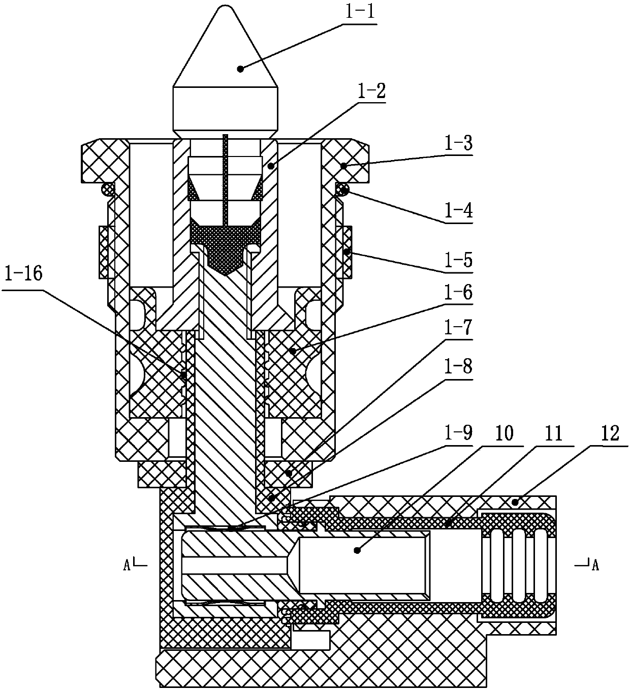
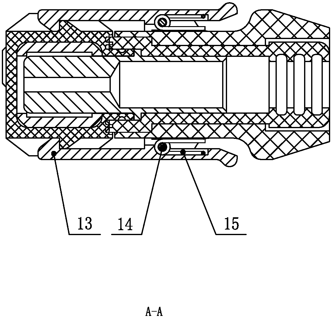
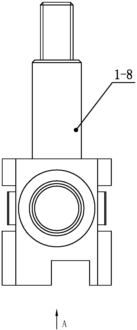
[0052] Embodiment 1: as Figure 1 to Figure 32 As shown, the wiring quick termination mechanism includes an electrical connector, and the electrical connector in this embodiment is a socket (structure such as Figure 1-Figure 23 shown) or plug (structured as Figure 24-31As shown), one end of the electrical connector is provided with a plug-in device for external plugging, the other end is provided with a terminal connected to the cable, and a locking sleeve body 12 is provided, and the locking sleeve body 12 is provided with The conductor 10, in order to prevent the conductor 10 from falling off during use, a cable sealing ring 11 can also be provided between the locking sleeve body 12 and the conductor 10, and the locking sleeve body 12 is connected to the electrical connector through a locking mechanism The terminals can be detachably installed to achieve quick termination. The locking mechanism can be installed on the locking sleeve body 12 or at the terminals on the elec...

Embodiment 2

[0072] Embodiment 2: the feature that differs from embodiment 1 in the present embodiment is: as Figure 33 As shown, there are multiple locking hooks 13 in the locking mechanism, and the locking hooks 13 are installed on the locking sleeve body 12, and the electrical connector forms a card slot matching the locking hooks 13. In the locked state, The locking hook 13 is snapped into the slot on the electrical connection.

[0073] When the conductor 10 is connected, the locking hook 13 shrinks toward the middle. After the conductor 10 is inserted in place, the locking hook 13 returns to its original state, and the locking hook 13 is clamped on the electrical connector. When the conductor 10 is pulled out, it shrinks. Lock hook 13, can pull out conductor 10.

Embodiment 3

[0074] Embodiment 3: the difference between this embodiment and the above-mentioned embodiment is: as Figure 34As shown, the locking mechanism includes a locking ring 18, which is connected to the locking sleeve body 12, and a rotatable steel ball 17 is arranged between the locking sleeve body 12 and the locking ring 18, and the conductor 10 is inserted into the , the locking sleeve body 12 and the locking ring 18 move towards the direction of the electrical connector, the steel ball 17 is clamped between the opening of the locking ring 18 and the locking sleeve body 12, and the locking ring 18 is away from the electrical connector A fixed ring 20 is formed at one end of the fixed ring 20, and a spring 19 is provided between the fixed ring 20 and the locking sleeve body 12. When the conductor 10 is inserted, the locking ring 18 compresses the spring 19 to move in the opposite direction of the electrical connector, and as the locking The sleeve body 12 continues to move toward...


PUM


Abstract

The invention relates to a rapid wiring terminating mechanism. The rapid wiring terminating mechanism comprises an electrical connector and a locking sleeve body, wherein the electrical connector is provided with a terminal end; the locking sleeve body is provided with an electrical conductor; and the locking sleeve body is detachably terminated with the wiring end of the electrical connector through a locking mechanism. According to the rapid wiring terminating mechanism in the invention, through the arrangement of the locking sleeve body and the arrangement of the locking mechanism on the locking sleeve body, after a cable is terminated, the locking sleeve is rapidly connected with the tail of a socket for locking, the installation of the connector and the wiring of a cable can be carried out simultaneously, the installation time is shortened, the installation efficiency is improved, the assembling of the cable can be realized by rapidly pulling a plug or the locking sleeve if the cable needs to be disassembled, the mechanism is simple in structure and convenient and rapid to use, the terminal of the cable is rapidly separated from the socket of the connector when maintenance isneeded, and the disassembling time is shortened, so that the loss is minimized.

Description

technical field [0001] The invention relates to the technical field of electric conduction application, in particular to a fast wiring termination mechanism. Background technique [0002] The current wiring method used between the electrical connector and the cable is generally to use a simple electric clip device to take power, but because this device is usually used in the automotive field, with the movement of the car or the shaking of the parts on the car, the electric clip It is very easy to loosen. During use, the staff or users usually wind a circle around the electric clip to fix the coil of the electric clip, or use a fixed connection method such as thread after the cable is connected. The above connection method is in During use, it takes a long time in the cable routing and installation process, which makes the installers work inefficient, and after the cable is attached to the connector, the size of the connector usually takes up a lot of space, which is too much...

Claims


Application Information

Patent Timeline
Patent Type & Authority Applications(China)
IPC IPC(8): H01R13/502H01R13/506H01R13/58
CPCH01R13/502H01R13/506H01R13/582
Inventor 王吉国
Owner ZHEJIANG ZHONGHANG ELECTRONICS
Why Eureka
Try Eureka