A concrete vibrating device for road construction

A concrete and road technology, applied in ceramic molding machines, manufacturing tools, etc., can solve the problems of poor vibration effect, high labor intensity, reduced labor intensity, etc., and achieve the effect of convenient transportation.

Active Publication Date: 2020-07-03
江苏上元正信电力发展建设有限公司
View PDF6 Cites 0 Cited by
  • Summary
  • Abstract
  • Description
  • Claims
  • Application Information

AI Technical Summary

Problems solved by technology

[0008] In order to make up for the deficiencies in the prior art, the present invention proposes a concrete vibrating device for road construction. The present invention is mainly used to solve the problems of high labor intensity, poor vibration effect and inability to adjust the position of the vibrating rod during the concrete vibrating process. The present invention realizes the revolution in a larger range when the vibrating rod rotates around its own axis through the arrangement of the vibration module and the planetary gear structure, realizes sufficient mixing of the concrete, and significantly reduces labor intensity, and through The setting of the adjustment module realizes the rapid adjustment of the distance between the vibrating rods; at the same time, the invention enables the transverse support to be turned over through the limit shaft, so that the vibrating rods can avoid collision when they are not working, and it is also convenient for transportation

Method used


Image

  • A concrete vibrating device for road construction
  • A concrete vibrating device for road construction
  • A concrete vibrating device for road construction

Examples


Embodiment Construction

[0025] In order to make the technical means, creative features, goals and effects achieved by the present invention easy to understand, the present invention will be further described below in conjunction with specific embodiments.

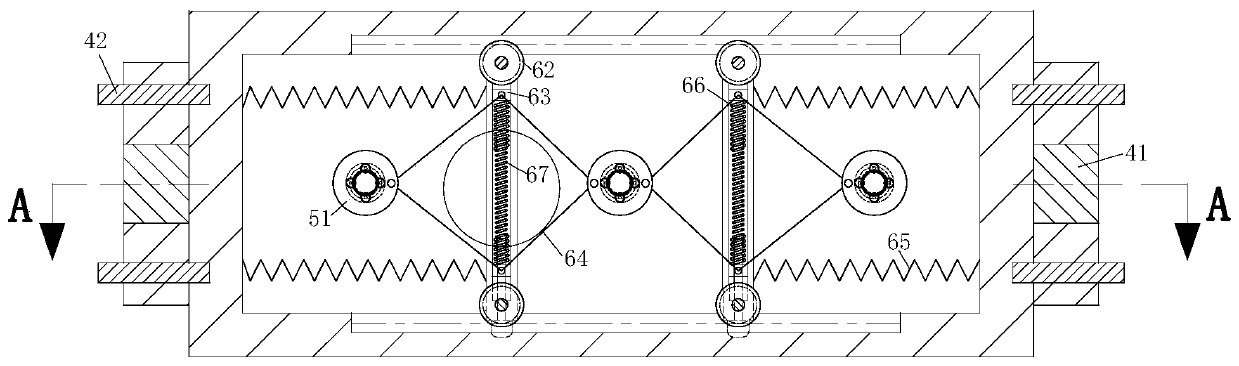
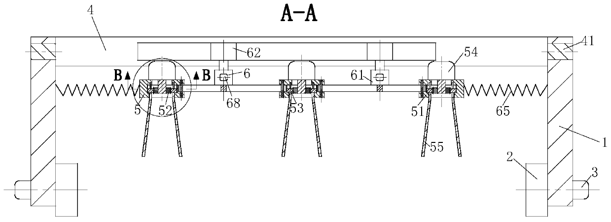
[0026] Such as Figure 1 to Figure 5 As shown, a concrete vibrating device for road construction according to the present invention includes a support 1, a travel wheel 2, a travel motor 3, a transverse support 4, a vibration module 5 and an adjustment module 6, and the support 1 The number is two, and the support 1 is symmetrically arranged on the ground through the traveling wheels 2; the traveling motor 3 is installed on the supporting seat 1, and the traveling motor 3 is used to drive the traveling wheels 2 to rotate; the transverse support 4 is arranged on the support 1, the transverse support 4 is a cuboid, and a rectangular through hole is vertically opened on the cuboid, and a chute is horizontally opened on the front and rear walls of the...


PUM


Abstract

The invention belongs to the technical field of concrete construction, and in particular relates to a concrete vibrating and compacting device for road construction, which comprises two support bases,walking wheels, walking motors, a transverse support, at least three vibration modules and a regulating module, the support bases are bilaterally and symmetrically arranged on the ground by the walking wheels; a walking motor is mounted on each support base and is used for driving the corresponding walking wheel to rotate; the transverse support is arranged on the support bases and is of a cuboid, a rectangular through-hole is arranged vertically at the cuboid, the front and rear walls of the rectangular through-hole are horizontally provided with a sliding groove, and the bottom of the sliding groove is horizontally provided with a toothed structure; the at least three vibration modules are installed on the transverse support, and are used to vibrate and compact the concrete; and the regulating module is used to regulate the spacing between the vibration modules. According to the concrete vibrating and compacting device for road construction, full vibration of concrete can be realized and labor intensity can be reduced; at the same time, the automatic adjustment of vibration bar spacing is realized.

Description

technical field [0001] The invention belongs to the technical field of concrete construction, in particular to a concrete vibrating device for road construction. Background technique [0002] Concrete is a raw material for construction, and its value is the largest in the construction industry. Because only it is the core material of the building. A building without concrete is like a living thing without flesh. Bones alone do not make a living organism. Therefore, in the construction industry, concrete is widely used. It can be said that anyone who works in the construction industry will use concrete as a substance, and its role is self-evident. For the most part, concrete already has a wide range of applications. [0003] Due to the thick slurry, poor fluidity and poor compaction density of concrete materials for construction, in the traditional technology, in order to overcome its defects, it is usually necessary to vibrate and compact the concrete before it sets. In...

Claims


Application Information

Patent Timeline
Patent Type & Authority Patents(China)
IPC IPC(8): B28B1/093
CPCB28B1/093
Inventor 王本勋葛旭樊雪花
Owner 江苏上元正信电力发展建设有限公司
Why Eureka
Try Eureka