

Headrest and method of manufacturing the headrest
a headrest and manufacturing method technology, applied in the field of headrests, can solve the problems of increasing the weight of the body, and achieve the effect of reducing the weight and increasing the number of parts
- Summary
- Abstract
- Description
- Claims
- Application Information
AI Technical Summary
Benefits of technology
Problems solved by technology
Method used
Image

Examples
Embodiment Construction
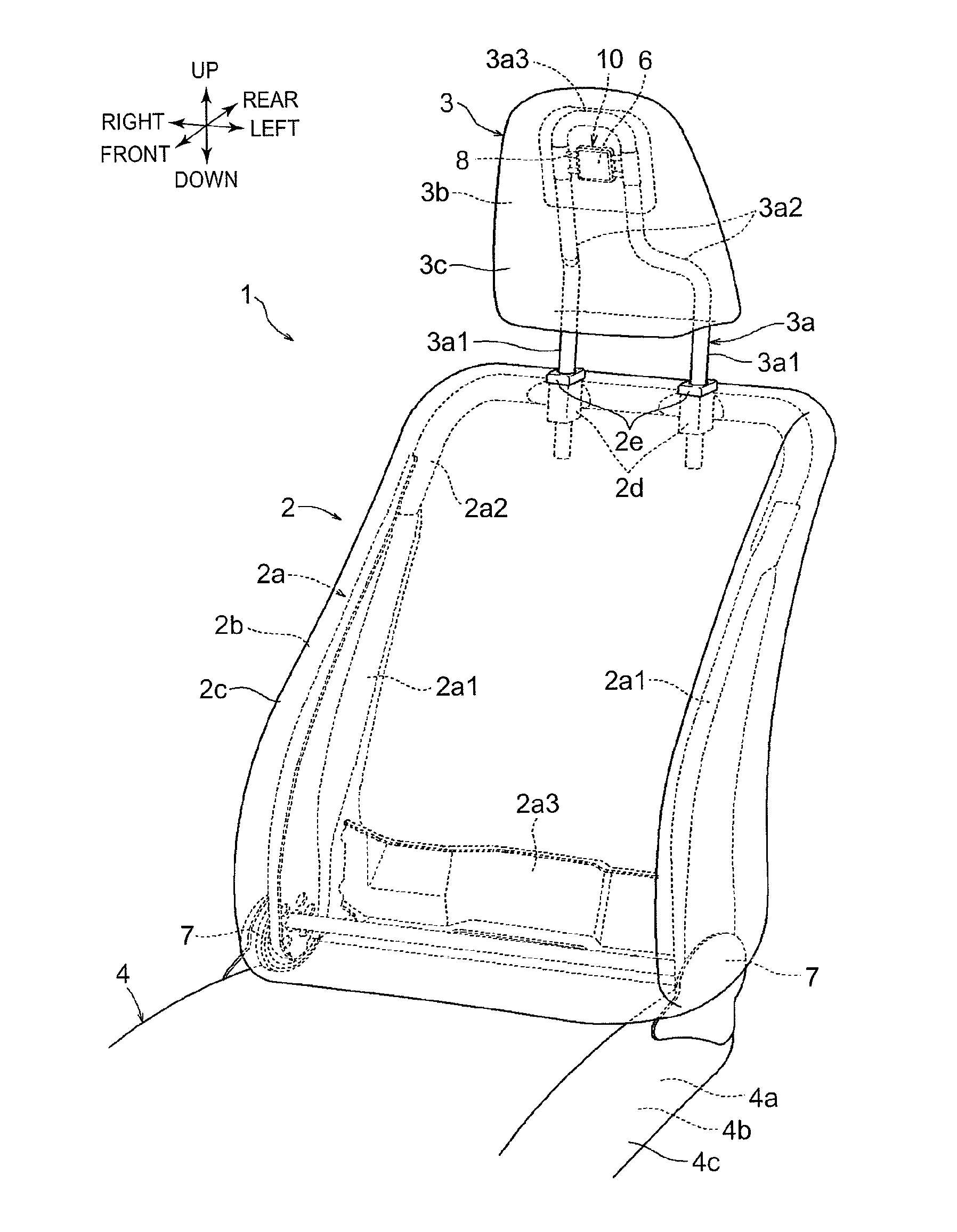
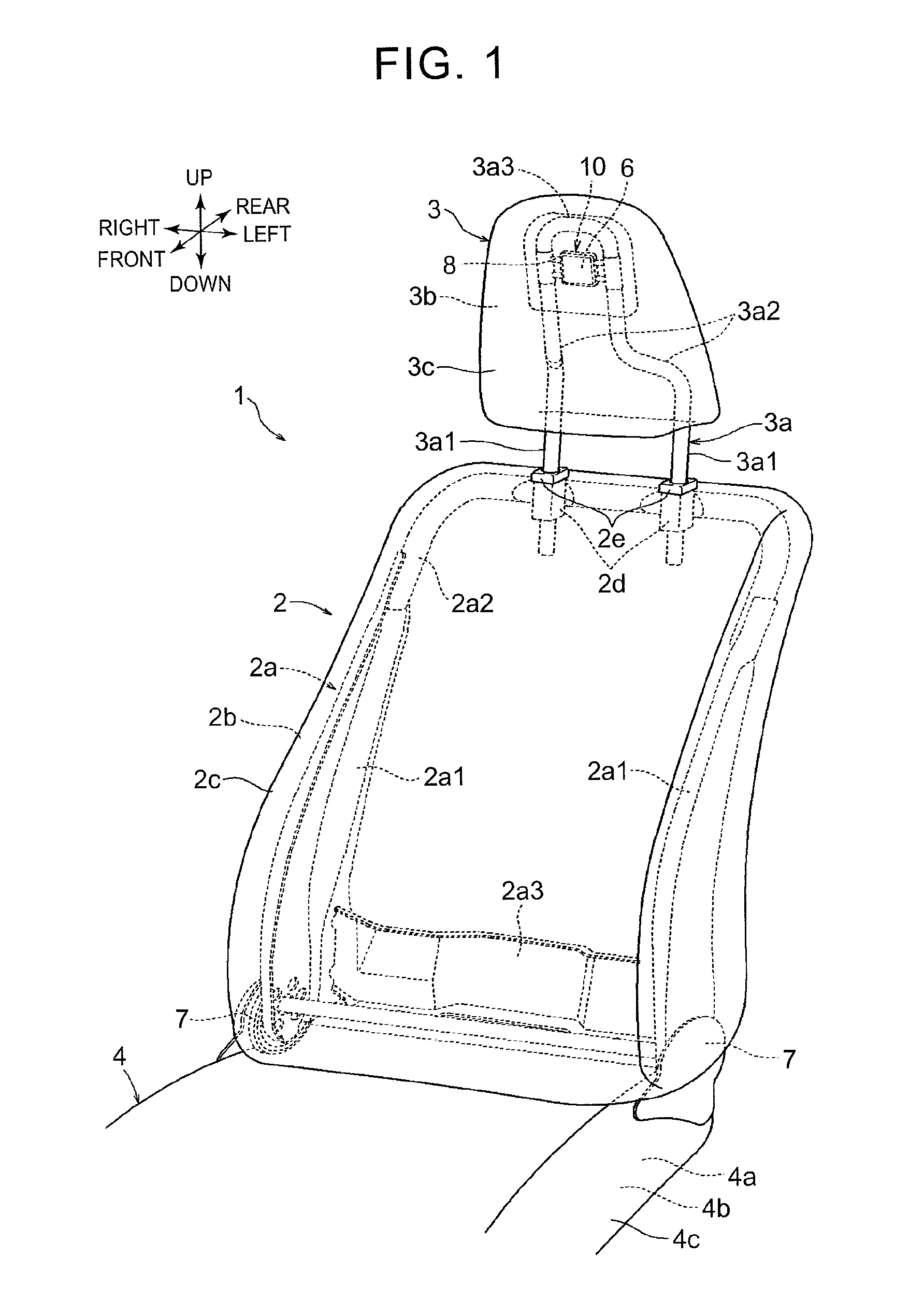
[0027]FIGS. 1 to 7 show one embodiment of the invention. This embodiment of the invention is an example in which the invention is applied to an automobile seat. In each of the drawings, respective directions of an automobile are denoted by arrows when the automobile seat is attached to the automobile. In the following description, the description of directions will be given with reference to those directions. An automobile seat 1 is equipped with a seat cushion 4 that serves as a seating portion, a seat back 2 that serves as a backrest, and a headrest 3 that supports a head. Lower end portions of the seat back 2 on both sides thereof are coupled, in an angularly adjustable manner, to rear end portions of the seat cushion 4 via recliners 7 respectively. The headrest 3 is the headrest according to the present embodiment of the invention.
[0028]As shown in FIG. 1, the seat back 2, the headrest 3 and the seat cushion 4 have frames 2a, 3a and 4a as skeletons, pads 2b, 3b and 4b as cushion...
PUM
| Property | Measurement | Unit |
|---|---|---|
| Weight | aaaaa | aaaaa |
Abstract
Description
Claims
Application Information