Vehicle joint control circuit, emergency parking braking method and rail traffic vehicle

A control circuit and emergency stop technology, which is applied in the field of rail transit, can solve the problems that the train parking brake control function cannot be realized, and achieve the effect of simplifying operation and enhancing safety

Active Publication Date: 2018-04-03
ZHUZHOU ELECTRIC LOCOMOTIVE CO +1
View PDF5 Cites 19 Cited by
  • Summary
  • Abstract
  • Description
  • Claims
  • Application Information

AI Technical Summary

Problems solved by technology

[0002] The semi-automatic coupler is the coupler that is connected to the coupler without any cable connection. When two trains equipped with semi-automatic couplers are connected, they will not...

Method used


Image

  • Vehicle joint control circuit, emergency parking braking method and rail traffic vehicle
  • Vehicle joint control circuit, emergency parking braking method and rail traffic vehicle
  • Vehicle joint control circuit, emergency parking braking method and rail traffic vehicle

Examples


Embodiment Construction

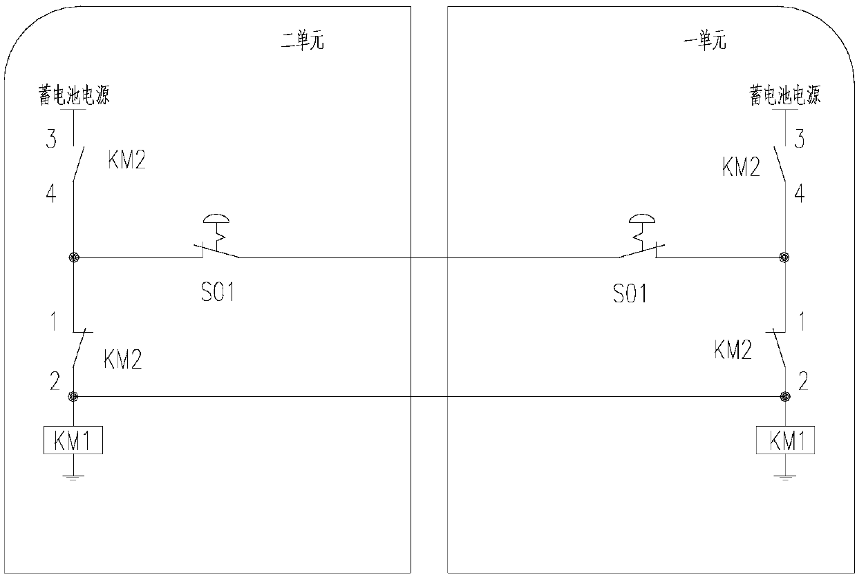
[0019] The linkage control circuit of the present invention includes two parts: the first part is an emergency parking brake application control circuit, and the second part is a parking brake application control circuit.

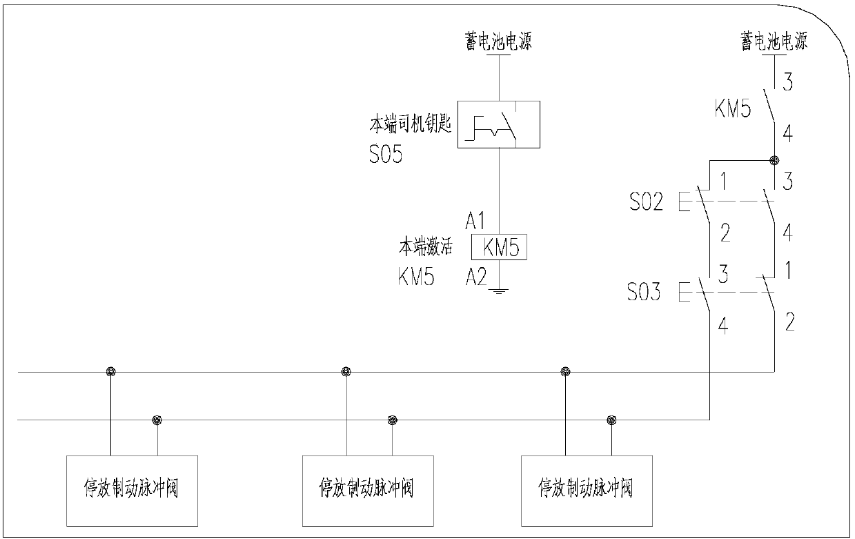
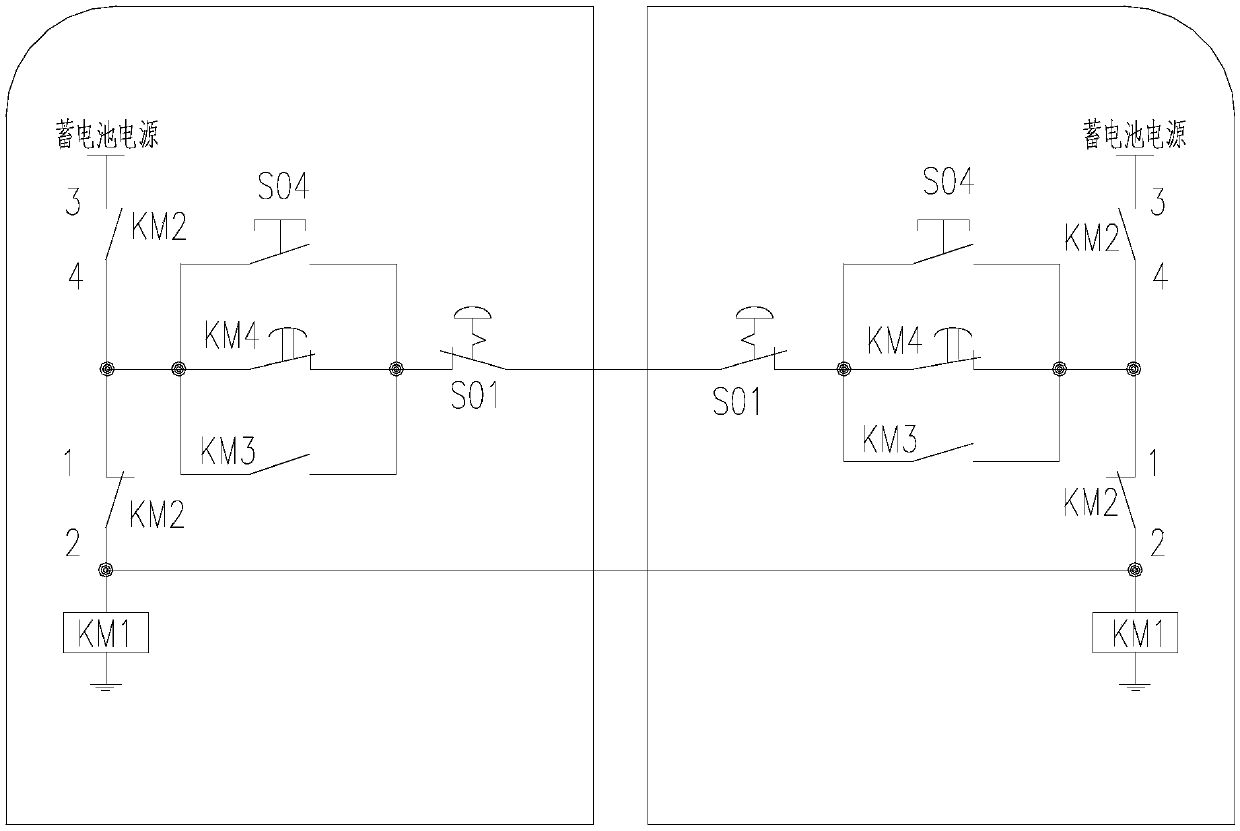
[0020] The two parts of the linked control circuit are as follows image 3 and Figure 4 As shown, for a single train, the circuit mainly includes 2 gain / loss delay relays of the whole vehicle, 2 train linkage relays, 2 emergency stop mushroom buttons, 2 emergency stop relays, and 2 parking brakes Release button, 2 parking brake application buttons, 2 uncoupling self-resetting buttons, coupler limit switch, parking brake pulse valve and some cables connecting these devices.

[0021] S01 represents the emergency stop mushroom button in the driver's cab; S02 represents the parking brake application self-resetting button; S03 represents the parking brake release self-resetting button; S04 represents the unhooking self-resetting button, when the driver presses...


PUM


Abstract

The invention discloses a vehicle joint control circuit, an emergency parking braking method and a rail traffic vehicle. The vehicle joint control circuit mainly comprises 2 gain/loss electricity delay relays of the whole vehicle, 2 train joint-already relays, 2 emergency parking mushroom buttons, 2 emergency parking relays, 2 parking braking release buttons, 2 parking braking applying buttons, 2unhooking automatic reset buttons, a car coupler limiting switch, a parking braking pulse valve and several cables, wherein the several cables are connected with the devices. The vehicle joint controlcircuit has the following functions of a, when two trains are accidentally unhooked during a joint rescue, parking braking is automatically applied to a faulty train, and emergency parking braking isautomatically applied to a rescue vehicle; b, when the two trains are in joint/unhooked, the rescue vehicle is prevented against emergency parking, and motions of high voltage break drop pantograph and the like are stopped; c, circuit logic itself for joint control does not influence the normal function of the single train.

Description

technical field [0001] The invention relates to the field of rail transit, in particular to a vehicle coupling control circuit, an emergency parking braking method, and a rail transit vehicle. Background technique [0002] The semi-automatic coupler is the coupler that is connected to the coupler without any cable connection. When two trains equipped with semi-automatic couplers are connected, they will not be able to communicate and control through the cable. The train parking braking control function of the train etc. will not be able to be realized. [0003] In the original technology of the semi-automatic coupler circuit, if an accidental decoupling occurs during the vehicle coupling rescue process, the driver of the vehicle can only control the rescue vehicle to apply the emergency parking brake or the faulty vehicle to apply the parking brake according to his own experience. [0004] figure 1 Shown is the original emergency stop control technology of a single train, ...

Claims


Application Information

Patent Timeline
IPC IPC(8): B60T13/74B60T7/20
CPCB60T7/20B60T13/74
Inventor 司尚卓黄志华李骏屈海洋陈小康吴桂林龚娟梁波
Owner ZHUZHOU ELECTRIC LOCOMOTIVE CO
Why Eureka
Try Eureka