Sealing ring and the use thereof

A technology of sealing ring and sealing lip, which is applied in the direction of engine sealing, mechanical equipment, engine components, etc., can solve the problems of not being installed, and achieve low-cost manufacturing, low assembly cost, reliable positioning and long-lasting effects

Active Publication Date: 2018-04-03
CARL FREUDENBERG KG
View PDF6 Cites 2 Cited by
  • Summary
  • Abstract
  • Description
  • Claims
  • Application Information

AI Technical Summary

Problems solved by technology

but without separately manufactured tensioning elements for stabilizing the sealing legs in the radial direction

Method used


Image

  • Sealing ring and the use thereof

Examples


Embodiment Construction

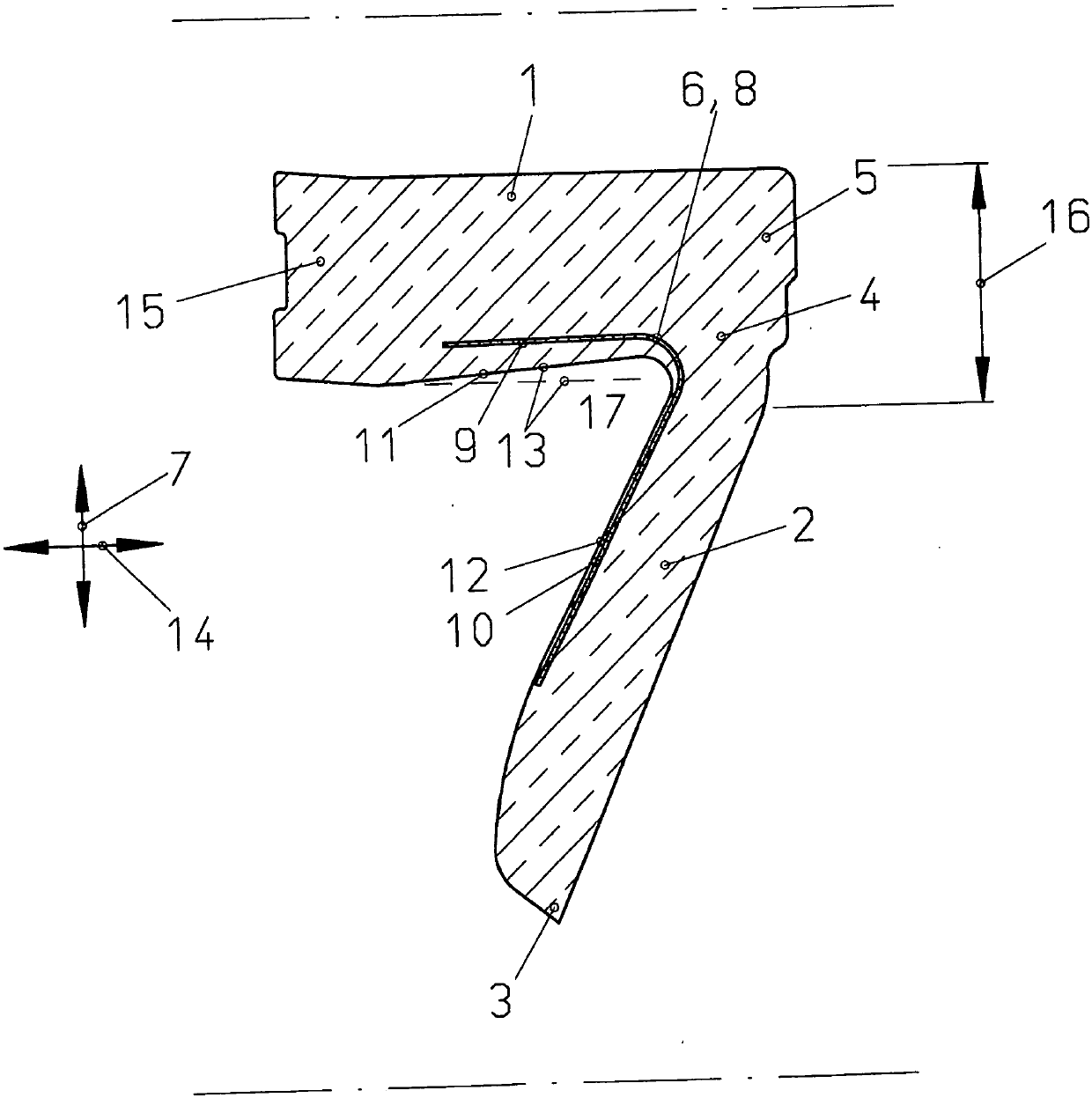
[0028] exist figure 1 The sealing ring shown in FIG. 2 is designed in the shape of a 7 and has, as tensioning element 6 , a likewise 7-shaped spring 8 which forms an integral component of the sealing ring and is completely surrounded by the sealing material of the sealing ring.

[0029]The sealing ring comprises a first axial leg 1 and a sealing leg 2 with a sealing lip 3 , wherein, depending on the application, the sealing leg 2 and the sealing lip 3 are arranged radially inside or radially outside of the sealing ring. Two axes of symmetry radially adjacent to the sealing lip 3 or radially adjacent to the first axial leg 1 are shown schematically. The sealing leg 2 is articulated on the first end side 5 of the axial leg 1 by means of an articulation joint 4 , wherein the joint 4 is arranged as far as possible from the sealing lip 3 in the radial direction 7 in order to be able to balance also here The large eccentricities of the machine elements are shown. This large eccent...


PUM


Abstract

The invention relates to a sealing ring and the use thereof. The sealing ring which, when viewed in cross section, is formed in the shape of a 7, has a first axial leg (1) and a sealing leg (2) that has a sealing lip (4), the sealing leg (2) being connected to a first end face (5) of the axial leg (1) by means of a joint (4), and has a clamping element (6) for stabilizing the sealing leg (2) in the radial direction. The clamping element (6) is annular and, when viewed in cross section, is formed by a 7-shaped spring (8), and has a second axial leg (9) and a stabilizing leg (10), the second axial leg (9) being connected to the first axial leg (1) and the stabilizing leg (10) being connected to the sealing leg (2). The invention also relates to the use of the sealing ring in a tunnel boringmachine or wind power plant.

Description

technical field [0001] The invention relates to a sealing ring and its use, wherein the sealing ring is formed in the shape of a 7 when viewed in cross section, the sealing ring comprises a first axial leg and a sealing leg with a sealing lip and includes a The tensioning element stabilizes the sealing leg in a direction, wherein the sealing leg is connected to the first end side of the axial leg by means of a joint. Background technique [0002] Such a sealing ring is known from EP 2988035 A1. Known sealing rings are used to seal off grease and include tensioning elements arranged in mounting grooves of the sealing ring. The mounting groove is arranged on the side of the sealing leg radially remote from the sealing lip, wherein the mounting groove has a mounting opening for the tensioning element on the side radially remote from the sealing lip, the mounting opening being formed by two Guide webs arranged adjacent to one another with a distance in the axial direction are ...

Claims


Application Information

Patent Timeline
Patent Type & Authority Applications(China)
IPC IPC(8): F16J15/3204F16J15/3248F16J15/3284
CPCF16J15/3204F16J15/3248F16J15/3284F16J15/3208F16J15/3212
Inventor K·米勒-尼胡斯H-W·京特F·舍恩贝格
Owner CARL FREUDENBERG KG
Why Eureka
Try Eureka