
Stable energy-saving LED lamp device

An LED energy-saving lamp, stable technology, applied in lighting devices, lighting device parts, light source fixing and other directions, can solve the problem of lamp caps that cannot meet the fixed size and different specifications, the difficulty of fixing, and the inability to fix the lamp caps of various sizes and different specifications. And other issues

Inactive Publication Date: 2018-04-03
CIXI KUANGYAN YINGYING BAMBOO PROD FACTORY GENERAL PARTNERSHIP
View PDF0 Cites 0 Cited by
  • Summary
  • Abstract
  • Description
  • Claims
  • Application Information

AI Technical Summary

Problems solved by technology

[0002] LED energy-saving lamps are widely used due to their low cost, high luminous efficiency, large light-emitting area, no glare, and no ghosting. LED energy-saving lamps are generally packaged by lamp caps and lamp tubes. However, most of the lamp caps are cylindrical structures, which are difficult to fix, and the lamp caps have different sizes and specifications. The general fixing parts can only fix the lamp caps of the same specification when fixing the lamp caps, and cannot meet the requirements of fixing different sizes. Standard lamp caps, so this greatly reduces the packaging work of lamp caps and lamp tubes, making the packaging efficiency low. Therefore, general fixing parts can no longer meet the needs of fixing existing lamp caps of various sizes and specifications.

Method used

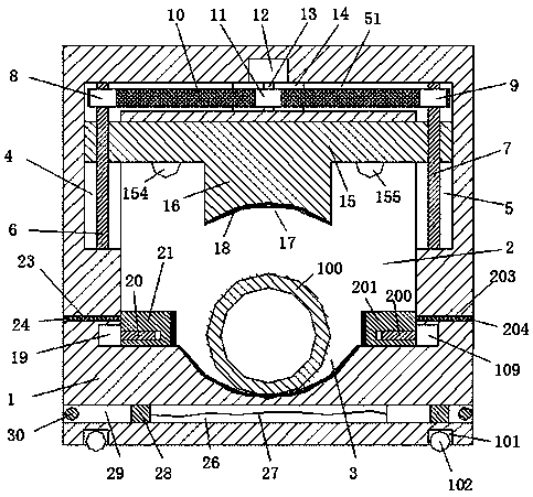

Image

  • Stable energy-saving LED lamp device
  • Stable energy-saving LED lamp device
  • Stable energy-saving LED lamp device

Examples


Embodiment Construction

[0020] The preferred embodiments of the present invention will be described in detail below in conjunction with the accompanying drawings, so that the advantages and features of the present invention can be more easily understood by those skilled in the art, so as to define the protection scope of the present invention more clearly.

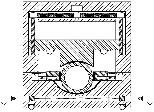
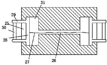
[0021] refer to Figure 1-4 The shown stable LED energy-saving lamp device includes a frame body 1 and an open cavity 2 arranged in the frame body 1 and passing through the front and back. The four corners of the bottom of the frame body 1 are provided with sinking cavities 101, four Rollers 102 are provided in each of the sunken chambers 101, so that the four rollers 102 can drive the frame body 1 to move. A left movable slot 4 and a right movable slot 5 are arranged respectively in the top of the left flat wall of the cavity 2 and the upper part of the right flat wall, and a movable slot connecting the left movable slot 4 and the right movable ...


PUM


Abstract

The invention discloses a stable energy-saving LED lamp device. The energy-saving LED lamp device comprises a frame body and an opening cavity with the front and the back communicating with each other, wherein the opening cavity is formed in the frame body; the four corners of the bottom of the frame body are provided with sunk cavities, a rolling wheel is arranged in each of the four sunk cavities in a rolling mode, a first semi-opening groove is formed in the middle of the bottom flat wall of the opening cavity, a left movable opening groove and a right movable opening groove are symmetrically formed in the top of the left flat wall of the opening cavity and the upper portion of the top of the right flat wall of the opening cavity respectively, and a through opening groove which connectsthe left movable opening groove and the right movable opening groove is formed in the top flat wall of the opening cavity; and a plate part capable of moving up and down is arranged in the opening cavity, a convex connection block is arranged in the middle of the bottom of the plate part, and a second semi-opening groove is formed in the bottom of the convex connection block. The energy-saving LED lamp device is reasonable in structure, easy to operate and convenient to carry; clamping of a lamp cap is safe and stable so that the lamp cap cannot deviate, the subsequent packaging operation ofthe lamp cap and a lamp tube can be facilitated, and meanwhile, lamp caps with different thicknesses can be clamped, so that the clamping and fixing cost of the lamp cap is greatly reduced; and the energy-saving LED lamp is high in packaging efficiency and suitable for popularization and use.

Description

technical field [0001] The invention relates to the technical field of LED energy-saving lamps, in particular to a stable LED energy-saving lamp device. Background technique [0002] LED energy-saving lamps are widely used due to their low cost, high luminous efficiency, large light-emitting area, no glare, and no ghosting. LED energy-saving lamps are generally packaged by lamp caps and lamp tubes. However, most of the lamp caps are cylindrical structures, which are difficult to fix, and the lamp caps have different sizes and specifications. The general fixing parts can only fix the lamp caps of the same specification when fixing the lamp caps, and cannot meet the requirements of fixing different sizes. Therefore, this greatly reduces the encapsulation work of the lamp cap and the lamp tube, making the encapsulation efficiency low. Therefore, the general fixing parts can no longer meet the requirements of fixing the existing lamp caps of various sizes and specifications. C...

Claims


Application Information

Patent Timeline
Patent Type & Authority Applications(China)
IPC IPC(8): F21K9/90F21V19/00F21Y115/10
CPCF21K9/90F21V19/002F21Y2115/10
Inventor 俞纯洁
Owner CIXI KUANGYAN YINGYING BAMBOO PROD FACTORY GENERAL PARTNERSHIP
Learn More