
A high voltage wire deicing device

A technology of high-voltage wires and resistance wires, which is applied in the field of high-voltage wire deicing devices, can solve problems such as production and life impacts, high-voltage wire breakage, and paralysis of photo-taking areas, so as to save manpower, prolong service life, and reduce risks. Effect

Active Publication Date: 2020-09-01
GUANGXI NANNING SHENGQIAN TECH DEV CO LTD
View PDF6 Cites 0 Cited by
  • Summary
  • Abstract
  • Description
  • Claims
  • Application Information

AI Technical Summary

Problems solved by technology

[0002] Every winter, most provinces and regions in southern my country will encounter ice and snow disasters. Many high-voltage power lines are crushed due to too much ice accumulation, or become paralyzed in the area, resulting in large-scale power outages, which have a great impact on production and life.
The existing deicing technology mainly adopts manual beating, aircraft spraying ice-melting agent, etc. In addition, there are methods such as coating special materials on the outside of high-voltage wires, but these methods are unsafe, low in efficiency, and high in cost
Many existing technologies wait until the high-voltage wires are frozen to remove the ice, which increases the difficulty of cleaning. Now it is necessary to design a model that can be installed on the wires for a long time to automatically de-ice or prevent wires from freezing. ice effect device

Method used


Image

  • A high voltage wire deicing device
  • A high voltage wire deicing device

Examples


Embodiment 1

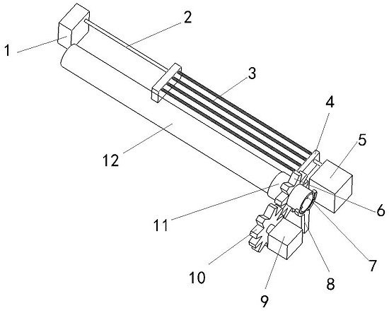
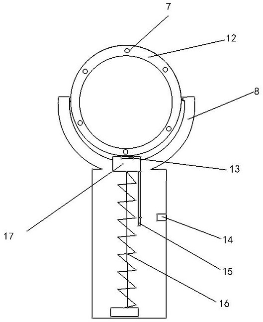
[0020] Such as figure 1As shown, a high-voltage wire deicing device includes a rotating device, a cutting device and a trigger device; the rotating device includes a sleeve 12, a driving gear 10, a driven gear 6, a sliding sleeve 11 and a motor three 9; The sleeve 12 is provided with a heating wire 7; the sleeve 12 wraps the high-voltage wires and has intervals between them; the sleeve 12 is arranged on the support rod 8; the sleeve 12 and the support rod 8 part of the groove is in contact; the inner interlayer of the sleeve 12 is provided with a plurality of heating wires 7; the heating wires 7 are arranged in the interlayer of the sleeve 12 in a circular manner and are spaced from each other; the driving The gear 10 is located on the motor three 9; the drive gear 10 is located on one side of the sleeve 12; the driven gear 6 is fixed on the sliding sleeve 11; between the driven gear 6 and the support rod 8 There is an interval; there is an interval between the driven gear 6 ...

Embodiment 2

[0023] Such as figure 1 As shown, a high-voltage wire deicing device includes a rotating device, a cutting device and a trigger device; the rotating device includes a sleeve 12, a driving gear 10, a driven gear 6, a sliding sleeve 11 and a motor three 9; The sleeve 12 is provided with a heating wire 7; the sleeve 12 wraps the high-voltage wires and has intervals between them; the sleeve 12 is arranged on the support rod 8; the sleeve 12 and the support rod 8 part of the groove is in contact; the inner interlayer of the sleeve 12 is provided with a plurality of heating wires 7; the heating wires 7 are arranged in the interlayer of the sleeve 12 in a circular manner and are spaced from each other; the driving The gear 10 is located on the motor three 9; the drive gear 10 is located on one side of the sleeve 12; the driven gear 6 is fixed on the sliding sleeve 11; between the driven gear 6 and the support rod 8 There is an interval; there is an interval between the driven gear 6...


PUM


Abstract

The invention discloses a high-voltage electric wire deicing apparatus. The high-voltage electric wire deicing apparatus comprises a rotating apparatus, a cutting apparatus and a triggering apparatus;the rotating apparatus comprises a sleeve, a driving gear, a driven gear, a sliding sleeve and a motor III; the cutting apparatus comprises a resistance wire, a resistance box, a steel wire rope, a motor I and a motor II; and the trigger apparatus comprises a supporting rod, a top block, a pressure sensor, a position sensor, a connecting rod and a spring column. By setting a transmission apparatus on an electric wire and by setting the cutting apparatus on the transmission apparatus, automatic and efficient deicing for a high voltage line can be realized; the high-voltage electric wire deicing apparatus has the characteristics of high practicability, relatively simple use, and capability of automatically and effectively protecting the high voltage wire from external damage, prolonging theservice life of the high voltage wire and saving human input; and in addition, manpower participation in the deicing process is not needed, so that the equipment can be controlled automatically according to weight of ice and snow for deicing, thereby greatly lowering danger existing in manual operation.

Description

technical field [0001] The invention belongs to the technical field of deicing, and relates to a high-voltage electric wire deicing device. Background technique [0002] Every winter, most provinces and regions in southern my country will encounter ice and snow disasters. Many high-voltage wires are crushed due to too much ice accumulation, or become paralyzed in the area, resulting in large-scale power outages, which have a great impact on production and life. Existing deicing technologies mainly use manual beating, spraying ice-melting agent on aircraft, etc. In addition, there are methods such as coating special materials on the outside of high-voltage wires, but these methods are unsafe, low in efficiency, and high in cost. Many existing technologies wait until the high-voltage wires are frozen to remove the ice, which increases the difficulty of cleaning. Now it is necessary to design a model that can be installed on the wires for a long time to automatically de-ice or ...

Claims


Application Information

Patent Timeline
Patent Type & Authority Patents(China)
IPC IPC(8): H02G7/16
CPCH02G7/16
Inventor 钟安祺范辉乐黄景明
Owner GUANGXI NANNING SHENGQIAN TECH DEV CO LTD
Learn More