
Charge and discharge control apparatus and method

A charge and discharge control and discharge capacity technology, applied in circuit devices, data exchange chargers, battery over-discharge protection, etc., can solve the problem of not considering the time when the maximum load occurs, and can not handle the actual load and the predicted situation when the situation is different and other problems, to achieve the effect of reducing demand costs, reducing peak power consumption and high economic benefits

Active Publication Date: 2018-04-03
INSTITUTE FOR INFORMATION INDUSTRY
View PDF2 Cites 0 Cited by
  • Summary
  • Abstract
  • Description
  • Claims
  • Application Information

AI Technical Summary

Problems solved by technology

The aforementioned first and second types of technologies do not consider the time when the maximum load actually occurs, while the third type of method cannot deal with the problem when the actual load is different from the predicted situation
Therefore, although there are technologies that use storage batteries to reduce user peak loads, the effects of these technologies need to be further improved.

Method used


Image

  • Charge and discharge control apparatus and method
  • Charge and discharge control apparatus and method
  • Charge and discharge control apparatus and method

Examples


Embodiment Construction

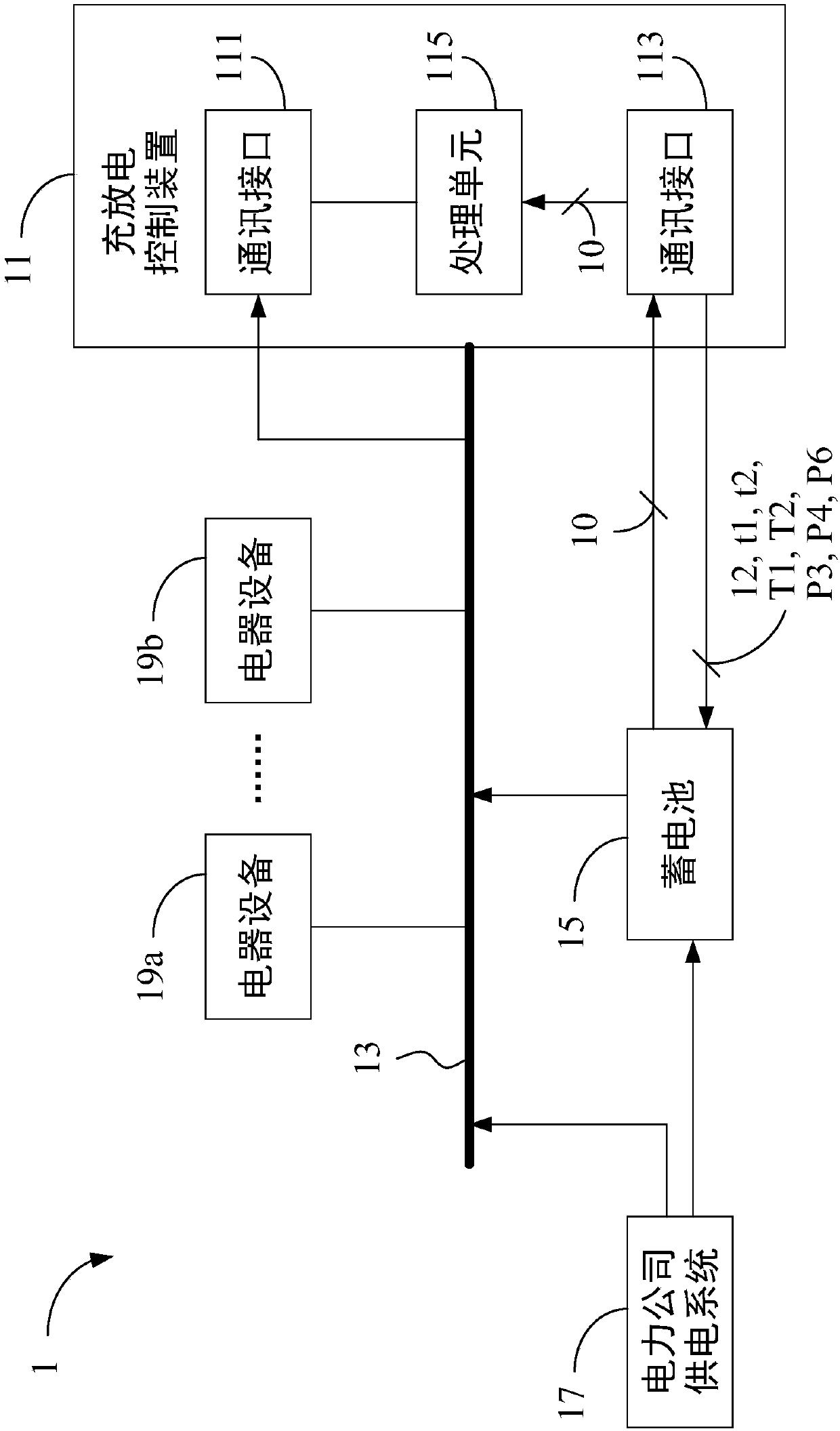
[0061] The charge and discharge control device and method provided by the present invention will be explained below through implementation. However, these embodiments are not intended to limit the present invention to be implemented in any environment, application or manner as described in these embodiments. Therefore, descriptions about the embodiments are only for the purpose of explaining the present invention, rather than limiting the scope of the present invention. It should be understood that in the following embodiments and drawings, elements that are not directly related to the present invention have been omitted and not shown, and the dimensions of each element and the ratio of dimensions between elements are for illustration only, and are not intended to limit the present invention range.

[0062] The first embodiment of the present invention is a power consumption system 1, the schematic diagram of its architecture is depicted in Figure 1A . The power consumption...


PUM


Abstract

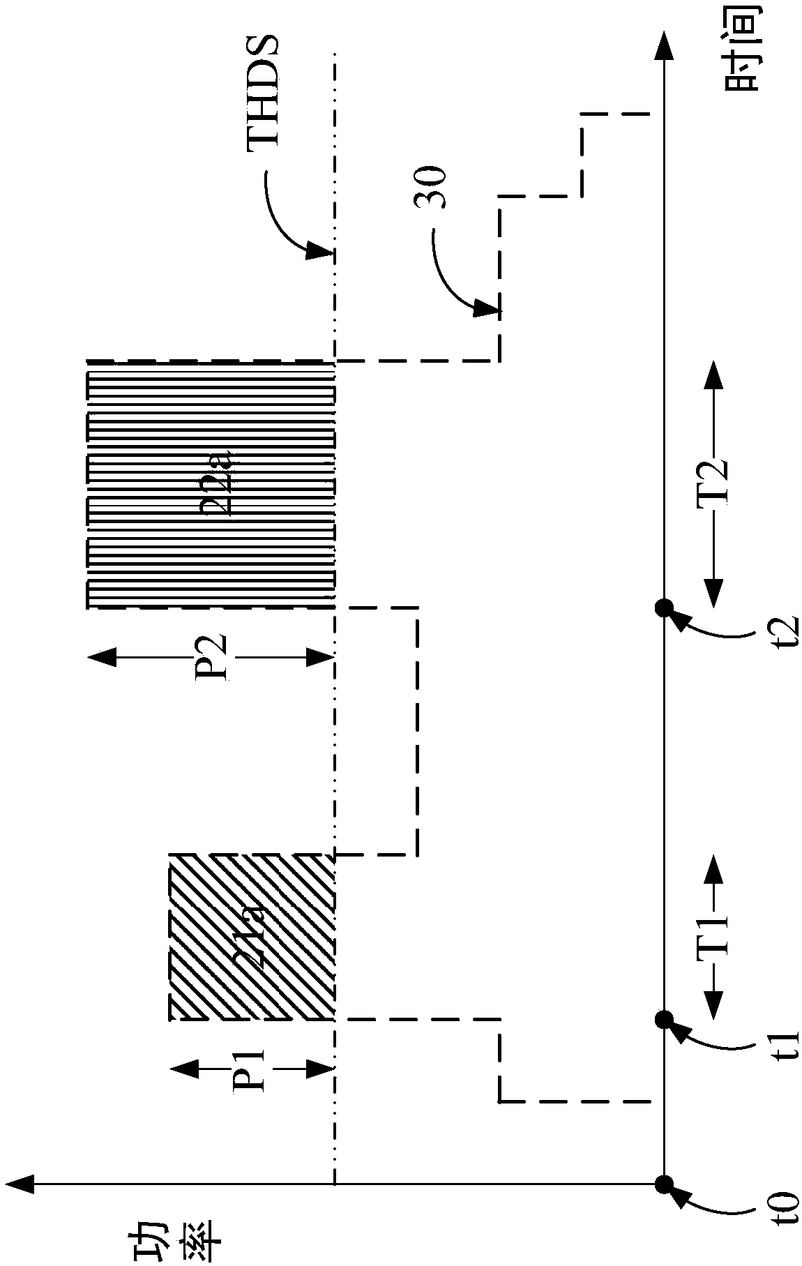
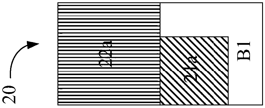
The invention provides a charge and discharge control apparatus and method. The charge and discharge control apparatus divides a stored electricity amount of a storage battery into a backup electricity amount and a plurality of predetermined discharge amount corresponding to a plurality of dispatching time points. Each of the dispatching time points corresponds to a dispatching period and a predetermined discharge power. The charge and discharge control apparatus receives a load parameter of an electric loop at each dispatching time point. Each load parameter carries a load power of the electric loop. The charge and discharge control apparatus performs the following operations at each dispatching time point: (i) deciding a real discharge power that the storage battery provides to the electric loop according to a dispatching threshold and the load power corresponding to the dispatching time point and (ii) updating the backup electricity amount according to the real discharge power and the predetermined discharge amount.

Description

technical field [0001] The invention relates to a charging and discharging control device and method. Specifically, the present invention relates to a charging and discharging control device and method for battery energy storage equipment (Battery Energy Storage System; BESS). Background technique [0002] Electricity charges charged by power companies to users generally include two categories, namely, energy charge and demand charge. The electricity charge is the charge derived from the total electricity used by the user within a certain period of time (for example: one month's billing period), and its pricing unit is "kilowatt hour (kWh)", also known as "degree". Regarding electricity costs, power companies usually implement a time-based electricity price system, setting different electricity price rates for different time intervals, so as to guide users to reduce electricity consumption during peak hours. In addition, the demand fee is the fee charged by the power compa...

Claims


Application Information

Patent Timeline
IPC IPC(8): H02J3/28
CPCH02J3/28H02J3/32H02J7/0068G05F1/66H02J2310/64H02J7/00034Y04S50/10Y04S20/222Y02B70/3225H02J7/00306
Inventor 吴瑞明
Owner INSTITUTE FOR INFORMATION INDUSTRY
Learn More