
Method and system for controlling distributed micro-grid parallel operation

A distributed, micro-grid technology, applied in the direction of single-network parallel feeding arrangement, AC network load balancing, photovoltaic power generation, etc., can solve the power fluctuation of the power grid, the impact of the power grid, and the difficulty in meeting the requirements of micro-grid system security and economic operation, etc. question

Active Publication Date: 2013-12-25
STATE GRID TIANJIN ELECTRIC POWER +3
View PDF0 Cites 0 Cited by
  • Summary
  • Abstract
  • Description
  • Claims
  • Application Information

AI Technical Summary

Problems solved by technology

[0003] At present, the micro-grid system composed of photovoltaic power generation system, wind power generation system, energy storage system and load, when the micro-grid is in the grid-connected mode, due to the uncertainty of the power generation power of the photovoltaic power generation system and wind power generation system, will cause serious damage to the power grid. A certain impact will affect the safe and stable operation of the entire power grid. The control strategy of the microgrid system is not perfect, and the real-time data monitoring, power generation and power load prediction are insufficient. impact, and did not consider the demand side response, it is difficult to meet the requirements of safe and economical operation of the microgrid system

Method used


Image

  • Method and system for controlling distributed micro-grid parallel operation
  • Method and system for controlling distributed micro-grid parallel operation
  • Method and system for controlling distributed micro-grid parallel operation

Examples


Embodiment Construction

[0020] In order to make the purpose, technical solution and advantages of the present invention more clear, the present invention will be further described in detail below in conjunction with the accompanying drawings and embodiments. It should be understood that the specific embodiments described here are only used to explain the present invention, not to limit the invention.

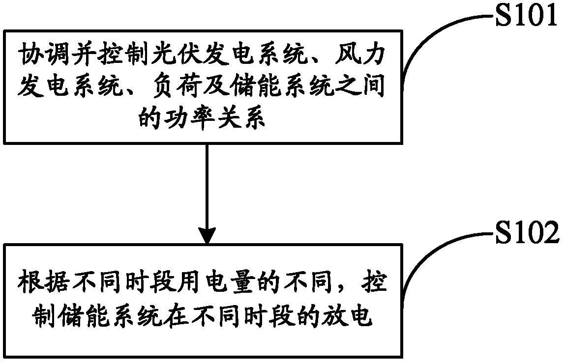
[0021] figure 1 It shows the implementation flow of the method for controlling the grid-connected operation of distributed microgrids provided by the embodiments of the present invention.

[0022] The method includes the following steps:

[0023] In step S101, coordinate and control the power relationship between the photovoltaic power generation system, the wind power generation system, the load and the energy storage system;

[0024] In step S102, the discharge of the energy storage system in different periods is controlled according to the difference in power consumption in different periods.

[...


PUM


Abstract

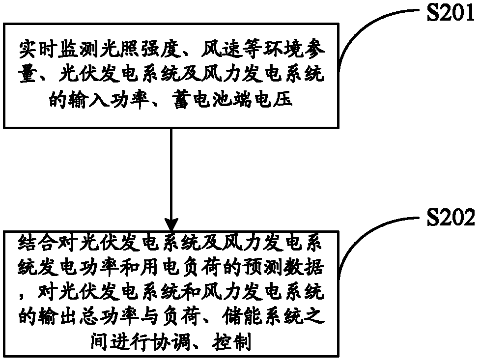
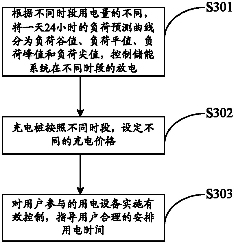
The invention belongs to the field of distributed micro-grid deployment and management, and provides a method and system for controlling distributed micro-grid parallel operation. The method is characterized in that through monitoring environment parameters such as illumination intensity, wind speed and the like as well as real-time data such as input power, storage battery end voltage and the like and by virtue of predicted data of electricity generation power and electricity utilization load, coordination control is carried out on the output total power of a photovoltaic generating system and a fan, load, a storage battery energy storage system so as to meet a requirement of system power balance; meanwhile, a load prediction curve of 24 hours are divided into a load valley, a load flat value, a load peak and a load top value according to different power consumption in different time periods; and a discharging policy of an energy storage system is arranged according to different time periods, a charging pile can set different charging prices according to different time periods, and electric equipment utilized by a user is subjected to effective control, thereby achieving the purpose of stabilizing the electric network power fluctuation, reducing the power equipment investment and achieving an optimal economic effect and a energy-saving effect.

Description

technical field [0001] The invention belongs to the field of distribution network dispatching and management, and in particular relates to a method and system for controlling the grid-connected operation of distributed micro-grids. Background technique [0002] A microgrid, also known as a distributed energy island system, systematically combines generators, loads, energy storage devices, and control devices to form a single controllable unit that supplies electricity and heat to users at the same time. Most of the power sources in the microgrid are micro power sources, that is, small units (less than 100kW) with power electronic interfaces, including micro gas turbines, fuel cells, photovoltaic power generation system batteries, and energy storage devices such as supercapacitors, flywheels, and batteries. The microgrid is connected to the user side and has the characteristics of low cost, low voltage, and low pollution. The microgrid can be connected to the large grid, and...

Claims


Application Information

Patent Timeline
Patent Type & Authority Patents(China)
IPC IPC(8): H02J3/38H02J3/28
CPCY02E10/763Y02E70/30Y02E10/566Y02E10/563Y02E10/766Y02E10/56Y02E10/76
Inventor 郜士其杨宇全杨磊龚博林昌年王庆平张鹏杨永柱
Owner STATE GRID TIANJIN ELECTRIC POWER
Learn More