Data transmission method and device

A data transmission method and technology of a data transmission device are applied in the directions of digital transmission systems, transmission systems, and multiple use of transmission paths.

Active Publication Date: 2018-04-03
DATANG MOBILE COMM EQUIP CO LTD
View PDF4 Cites 9 Cited by
  • Summary
  • Abstract
  • Description
  • Claims
  • Application Information

AI Technical Summary

Problems solved by technology

[0011] The disadvantage of the existing technology is that, taking the current 5G system as an example, there is no solution that can use dynamic uplink and downlink resource division for data transmission

Method used


Image

  • Data transmission method and device
  • Data transmission method and device
  • Data transmission method and device

Examples


Embodiment 1

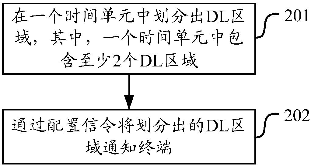
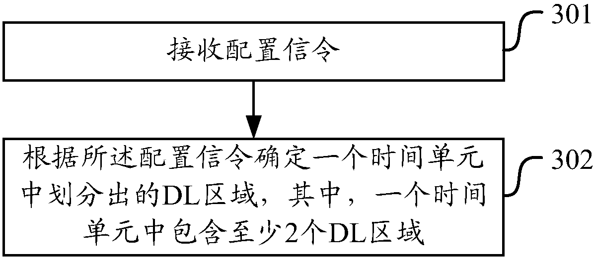
[0239] Figure 4 It is a schematic diagram of system uplink and downlink resource division and corresponding relationship with TA and / or switching time in Embodiment 1, Figure 5 It is a schematic diagram of system uplink and downlink resource division and corresponding relationship without TA and / or switching time in Embodiment 1, as shown in Figure 4 As shown, it is assumed that the base station determines to divide a time unit into two DL areas and one UL area, and there is a blank area or GP area between the DL area and the UL area. This is to meet the TA (Timing Advance) of the UL. Demand, DL to UL switching time, the reserved area may also be determined by considering factors such as neighbor cell interference; of course, if TA or switching time or anti-interference is not required, the blank part or GP part may not exist, such as Figure 5 As shown; the corresponding relationship between the DL area and the UL area can be directly agreed or configured, for example, th...

Embodiment 2

[0262] Figure 12 It is a schematic diagram of system uplink and downlink resource division and corresponding relationship with TA and / or switching time in Embodiment 2, Figure 13 It is a schematic diagram of system uplink and downlink resource division and corresponding relationship without TA and / or switching time in Embodiment 2, as shown in Figure 12 As shown in , it is assumed that the base station determines to divide a time unit into two DL areas and two UL areas, and the space between the DL area and the UL area is a blank area or GP area, in order to meet the TA requirements of UL and the switching time from DL to UL , It is also possible to consider the reserved area determined by factors such as neighbor cell interference; of course, if TA or switching time or anti-interference is not required, the blank part or GP part may not exist, such as Figure 13 As shown; you can directly agree or configure the corresponding relationship between the DL area and the UL are...


PUM


Abstract

The invention discloses a data transmission method and device, and the method comprises the steps: carrying out the dividing of DL regions in a time unit, wherein the time unit comprises at least twoDL regions; notifying a terminal of the DL regions through a configuration signal after dividing; enabling the terminal to receive the configuration signal; and determining the DL regions divided fromone time unit according to the configuration signal. According to the invention, at least two DL detection regions are defined in one time unit, and the terminal detects the downlink transmission ineach detection region. When the downlink transmission is detected, the ACK/NACK feedback is carried out in an uplink region corresponding to the downlink region. Because a plurality of downlink regions can be divided from one time unit and each downlink region defines the feedback and scheduling relation, the method can improve the scheduling flexibility and utilization rate of system resources.

Description

technical field [0001] The invention relates to the technical field of wireless communication, in particular to a data transmission method and device. Background technique [0002] In the existing LTE (Long Term Evolution, long term evolution) system, the following frame structure is defined for TDD (Time Division Duplex, time division duplex). [0003] figure 1 A schematic diagram of using frame structure type 2 for the LTE TDD system. As shown in the figure, the LTE TDD system uses frame structure type 2 (frame structure type 2, FS2 for short), and uplink and downlink transmission use different subframes or different time slots on the same frequency. Each 10ms radio frame consists of two 5ms half-frames, and each half-frame contains five subframes with a length of 1ms. The subframes in FS2 are divided into three categories: downlink subframes, uplink subframes and special subframes. Each special subframe consists of DwPTS (Downlink PilotTime Slot, downlink transmission t...

Claims


Application Information

Patent Timeline
Patent Type & Authority Applications(China)
IPC IPC(8): H04L5/00
CPCH04L5/0055H04L5/0044H04L5/0094H04L5/1469H04W72/0446H04W72/23H04L5/14
Inventor 高雪娟潘学明郑方政
Owner DATANG MOBILE COMM EQUIP CO LTD
Why Eureka
Try Eureka