Signal display method and system based on GIS (geographic information system) map

A GIS map and signal display technology, applied in the direction of image communication, TV system components, digital output to display devices, etc., can solve the problem of wrong estimation of target area area, inconvenient use, occupation of video wall memory, etc., to achieve scheduling High efficiency, ensuring the effect of search efficiency

Active Publication Date: 2018-04-03
GUANGDONG VTRON TECH CO LTD
View PDF7 Cites 2 Cited by
  • Summary
  • Abstract
  • Description
  • Claims
  • Application Information

AI Technical Summary

Problems solved by technology

The first search method needs to pre-allocate each video point with its own number and the name of the location where the video point is installed. During the scheduling process, complex signal names or long lists are presented, which is not easy to use. Convenient, not intuitive, and slow to find
The latter two search methods are prone to miscalculation of the area of ​​the target area, resulting in not being able to select the video point that is really needed, which is inconvenient to use, and the efficiency of scheduling the signal of the video point is greatly reduced.
In addition, in this patent, both the map and the surveillance video are displayed on the video wall, and all operations are directly displayed on the video wall. On the one hand, the map occupies the display space of the video wall, and on the other hand, all operations are performed directly on the video wall. These include the display of GIS maps, the display and search of video points, etc., which will occupy the memory of the video wall, resulting in low efficiency in the search of video points and low display efficiency of the video wall

Method used


Image

  • Signal display method and system based on GIS (geographic information system) map
  • Signal display method and system based on GIS (geographic information system) map
  • Signal display method and system based on GIS (geographic information system) map

Examples


Embodiment Construction

[0028] The present invention will be further elaborated below in conjunction with the accompanying drawings.

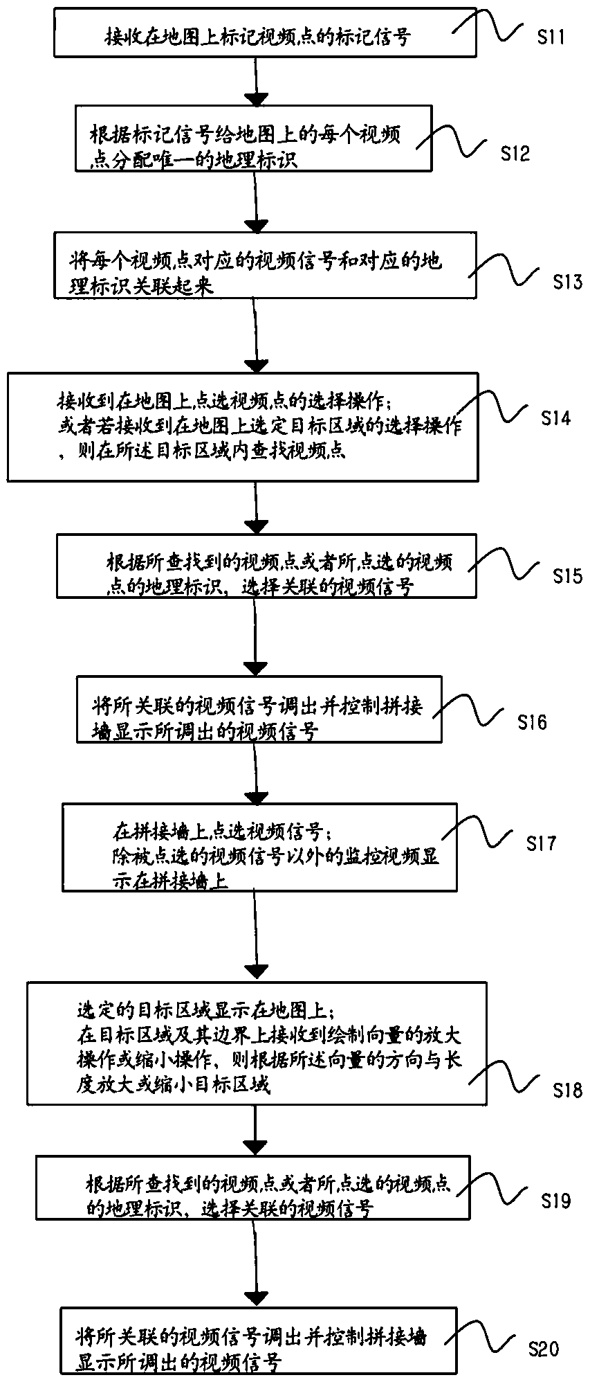
[0029] figure 1 It is a flow chart of an embodiment of the method of the present invention, a signal display method based on a GIS map, the method is used in a splicing wall, the splicing wall is controlled by a control device, and a GIS electronic map is displayed on the control device, step S11 ~S16 is the processing steps of the control device, specifically:

[0030] S11. Receive a marking signal for marking video points on the map.

[0031] S12. Assign a unique geographic identifier to each video point on the map according to the marker signal.

[0032] S13. Associating the video signal corresponding to each video point with the corresponding geographic identifier.

[0033]Steps S11-S13 associate the video point, geographic identifier, and video signal. The video point is equivalent to the camera device, and the camera device is marked on the GIS electronic ma...


PUM


Abstract

The invention relates to the field of large screen splicing display, in particular to a signal display method and system based on a GIS (geographic information system) map. The method is used for a spliced wall controlled by a control device, and the GIS electronic map is displayed on the control device. The method comprises a control device processing step particularly including: receiving marking signals of marking video points on the map; distributing a sole geographic identifier for each video point on the map according to the marking signals; associating a video signal corresponding to each video point with the corresponding geographic identifier; searching the video points in a target area if receiving the selection operation of clicking the video points on the map or receiving the selection operation of selecting the target area on the map; selecting associated video signals according to the searched video points or the geographic identifiers of the clicked video points; callingthe associated video signals and controlling the video signals called by spliced wall display.

Description

technical field [0001] The invention relates to the field of large-screen mosaic display, in particular to a signal display method and system based on a GIS map. Background technique [0002] At present, video surveillance is widely used in various fields of urban management, including security, traffic police, emergency command and other fields. In some big cities or megacities, the number of surveillance video points can reach tens of thousands or even hundreds of thousands, covering almost every corner of the city. Conventional video surveillance based on a large screen is to drag the required surveillance video into the signal callout and control unit for display; although the number of video surveillance is large, the video display is relatively fixed, it is not convenient to switch signals at will, and the work efficiency is low . [0003] The patent application number CN201110217788.8 discloses a method and device for video monitoring and display based on GIS maps. ...

Claims


Application Information

Patent Timeline
Patent Type & Authority Applications(China)
IPC IPC(8): H04N5/268G06F3/14G06F17/30
CPCG06F3/1446G06F16/78H04N5/268
Inventor 马庆张奕文
Owner GUANGDONG VTRON TECH CO LTD
Why Eureka
Try Eureka