Armrest

An armrest and pivot technology, applied in the field of armrest devices, can solve problems such as inability to adjust the bending angle, achieve the best market potential and increase comfort

Active Publication Date: 2019-12-06
PAO SHEN ENTERPRISES
View PDF1 Cites 3 Cited by
  • Summary
  • Abstract
  • Description
  • Claims
  • Application Information

AI Technical Summary

Problems solved by technology

[0002] It is a common design to add armrests on both sides of the seat for users to place their arms. The original armrests are mostly fixed and cannot be adjusted according to the user's body size, arm length, and customary bending angles.
[0003] Therefore, the prior art, as shown in US Patent No. US 20030030317A1, is a handrail device that can adjust the moving position and angle to increase the comfort of use. In order to avoid the adjusted position and angle from moving, the existing In the technology, a protruding point and a plurality of corresponding recesses are respectively provided on a sliding seat and a connecting rod, and the temporary positioning at different positions and angles is achieved by engaging the protruding point with different recesses Effect, yet, because described dimples are all fixed and the position of each dimple has a certain interval, if the angle that the user feels the most comfortable just in time between the positions of two dimples, the user will only be able to succumb to the position of the two dimples. Uncomfortable angles, like this, take away the beauty of designing an adjustable feature for added comfort

Method used


Image

  • Armrest
  • Armrest
  • Armrest

Examples


Embodiment Construction

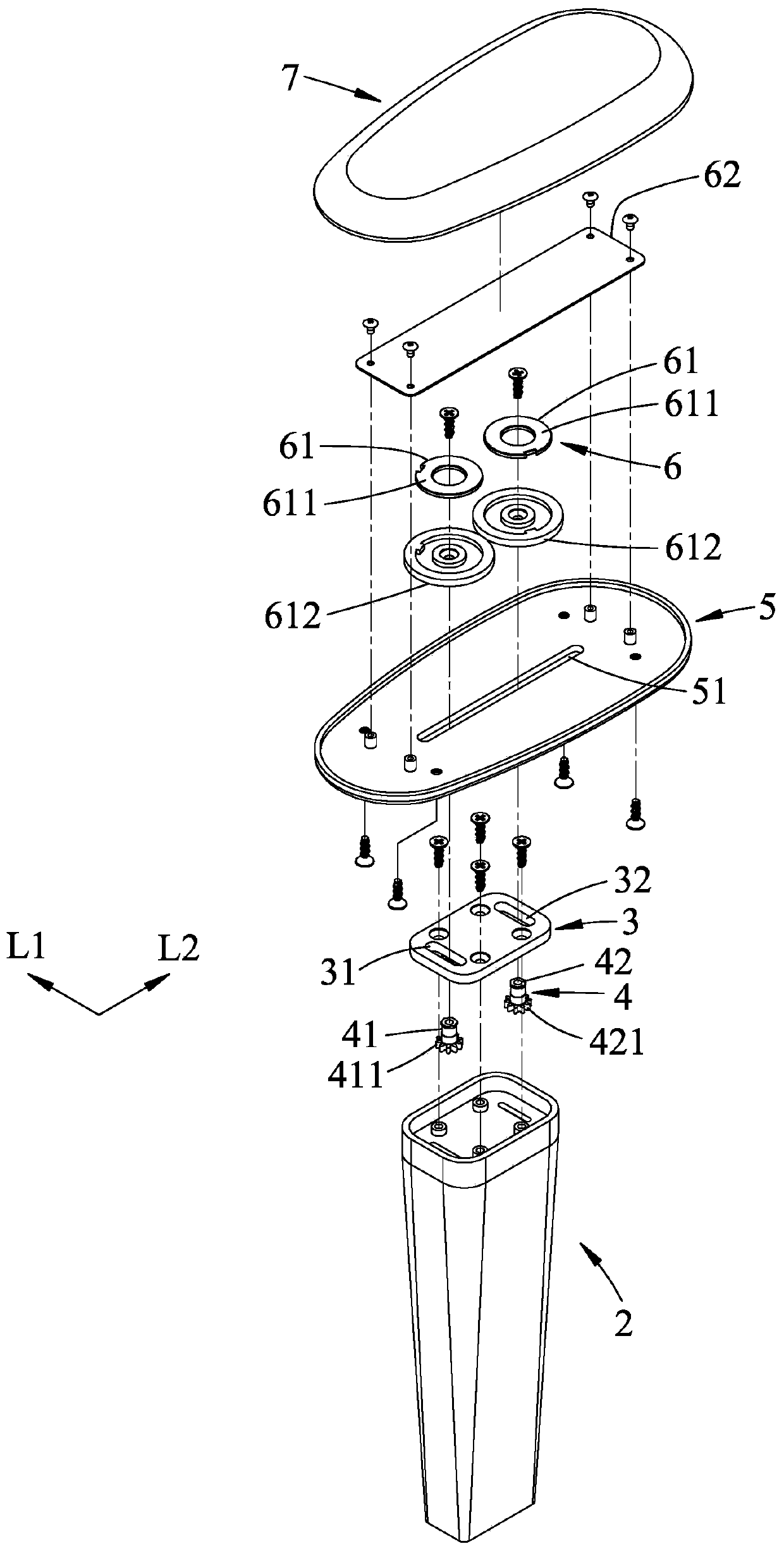
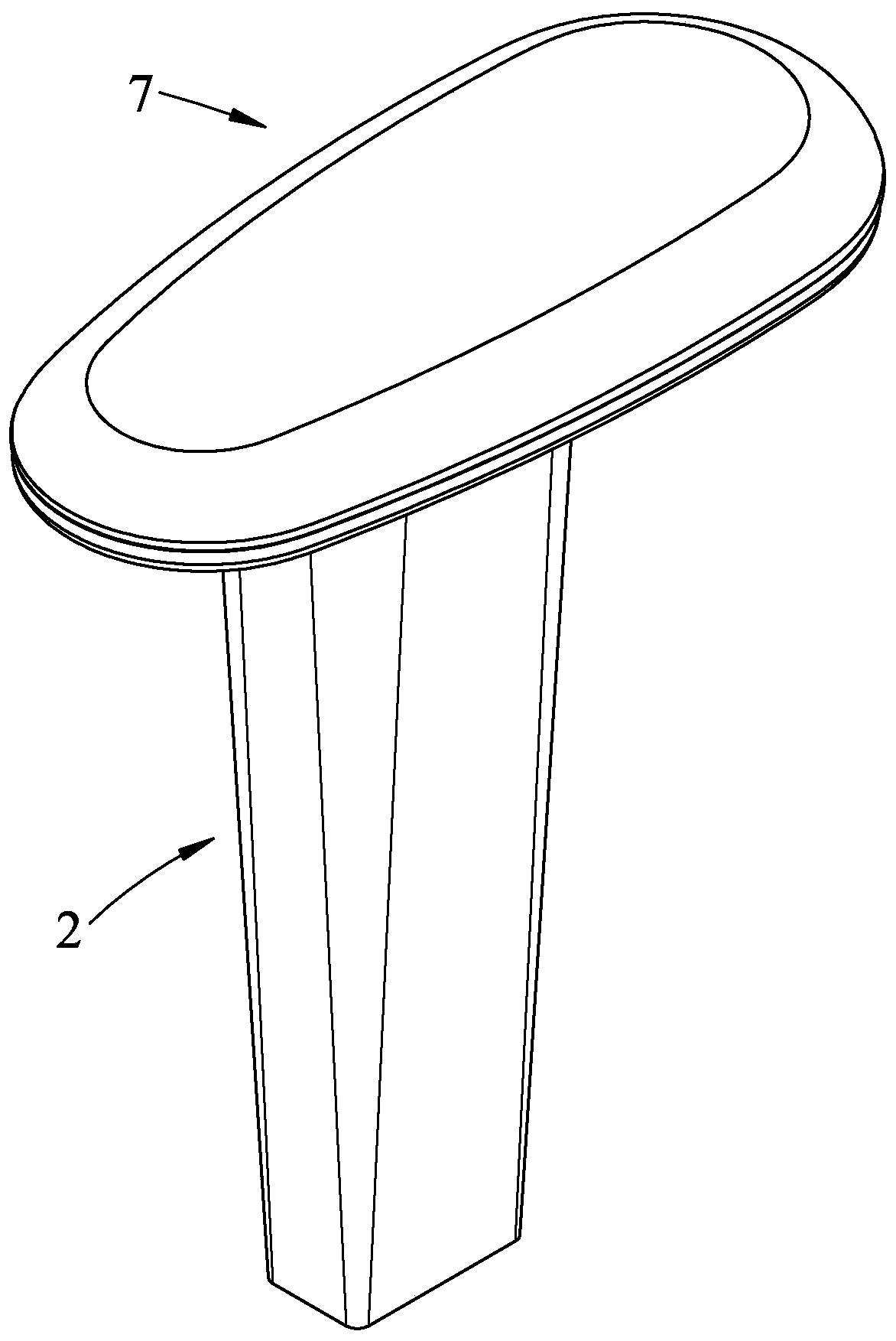
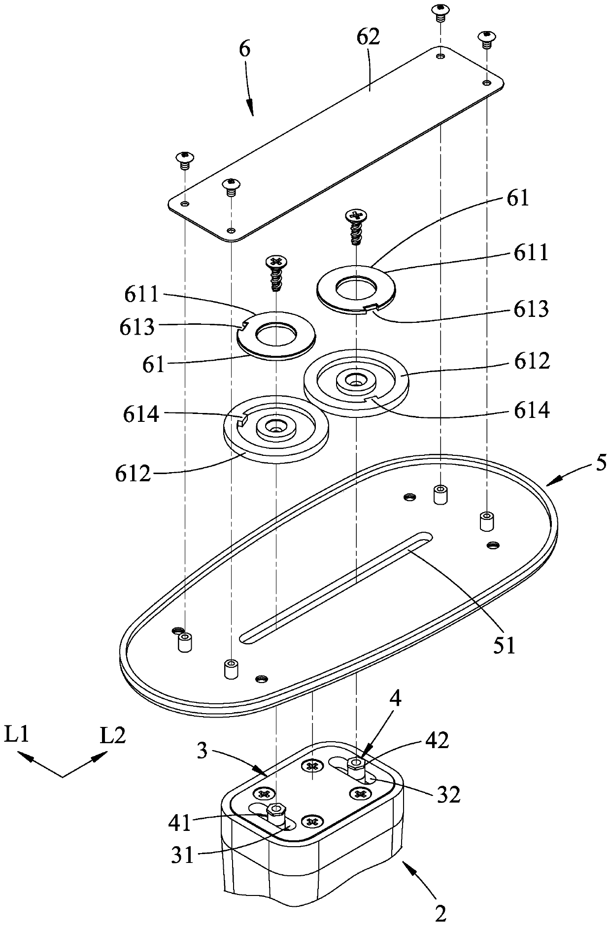
[0030] refer to figure 1 , figure 2 and image 3 , an embodiment of the armrest device of the present invention, in actual application, is suitable for setting two embodiments at the same time on the left and right sides of a seat (not shown), so that the hands of the user can be placed respectively.

[0031] This embodiment includes a base 2 , a fixing plate 3 , a pivot unit 4 , an armrest plate 5 , a positioning unit 6 , and a cushion 7 .

[0032] The base 2 is suitable for being fixed on one of the left and right sides of the seat, so as to provide a suitable height for the user to place the arms.

[0033] The fixed plate 3 is fixedly arranged on the base 2, such as figure 1 , 3 As shown in , it is fitted and locked in the depression at the top of the base 2 to increase the privacy and aesthetics of the mechanism so that the user can figure 2 When viewed from the upper angle shown, the inner workings are completely invisible. The fixing plate 3 includes a first movi...


PUM


Abstract

The invention relates to a handrail device which comprises a base, a fixed plate, a first pivot, a second pivot, a handrail plate and a positioning unit. The fixed plate comprises a first moving groove extending along a first direction; the first pivot is arranged in the first moving groove in a penetrated manner; the second pivot is arranged on the fixed plate; the handrail plate comprises a sliding groove extending along a second direction and the first and second pivots are arranged in the sliding groove in a penetrated manner; the positioning unit comprises a positioning module and a positioning plate with a magnetic attraction force with the positioning module; the handrail plate moves relative to the fixed plate to drive one of the positioning module and the positioning plate to moverelative to the other one; the magnetic attraction force will generate resistance for the movement of the handrail plate relative to the fixed plate. Therefore, the moving position and the rotating angle of the handrail plate can be adjusted in a section-free manner, the using comfort level can be enhanced, and the handrail device has a more excellent market potential.

Description

technical field [0001] The invention relates to an armrest device, in particular to an armrest device suitable for being installed on both sides of a seat. Background technique [0002] It is a common design to add armrests on both sides of the seat for users to place their arms. Most of the original armrests are fixed and cannot be adjusted according to the user's body size, arm length, or customary bending angle. [0003] Therefore, the prior art, as shown in US Patent No. US 20030030317A1, is a handrail device that can adjust the moving position and angle to increase the comfort of use. In order to avoid the adjusted position and angle from moving, the existing In the technology, a protruding point and a plurality of corresponding recesses are respectively provided on a sliding seat and a connecting rod, and the temporary positioning at different positions and angles is achieved by engaging the protruding point with different recesses Effect, yet, because described dimpl...

Claims


Application Information

Patent Timeline
Patent Type & Authority Patents(China)
IPC IPC(8): A47C7/54
CPCA47C7/54
Inventor 林振祐陈荣丰
Owner PAO SHEN ENTERPRISES
Why Eureka
Try Eureka