Tibial tunnel traction suture guide cannula for arthroscopic posterior cruciate ligament reconstruction

A cruciate ligament and traction wire technology, applied in the field of medical devices, can solve the problems of time-consuming operation, difficulty in wire manipulation, and increase in surgical incisions, and achieve the effects of reducing the risk of vascular and nerve damage, saving operation time, and simplifying operation steps.

Active Publication Date: 2018-04-06
ZHONGSHAN HOSPITAL XIAMEN UNIV
View PDF5 Cites 0 Cited by
  • Summary
  • Abstract
  • Description
  • Claims
  • Application Information

AI Technical Summary

Problems solved by technology

However, since the posterior cruciate ligament is located behind the knee joint and is adjacent to the blood vessels and nerves of the popliteal fossa, and because the tibial insertion of the posterior cruciate ligament is covered by soft tissue, the operation needs to be guided from the tibial tunnel under direct vision through the posterior medial and posterior lateral incisions. The traction wire is inserted into the bone tunnel. This method has a large surgical trauma and increases the surgical incision. At the same time, the operation through the posterior incision may injure the blood vessels and nerves of the popliteal fossa.
Another method is to repeatedly push the steel wire into the joint cavity through the anteromedial or anterolateral incision under non-direct vision by bending and pulling the steel wire after the bone tunnel is drilled. occlusion, the operation of introducing the guide wire is very difficult, and often cannot succeed at one time, and requires repeated operations, which consumes a lot of operation time

Method used


Image

  • Tibial tunnel traction suture guide cannula for arthroscopic posterior cruciate ligament reconstruction
  • Tibial tunnel traction suture guide cannula for arthroscopic posterior cruciate ligament reconstruction
  • Tibial tunnel traction suture guide cannula for arthroscopic posterior cruciate ligament reconstruction

Examples


Embodiment 1

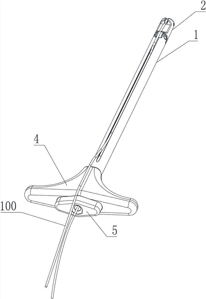
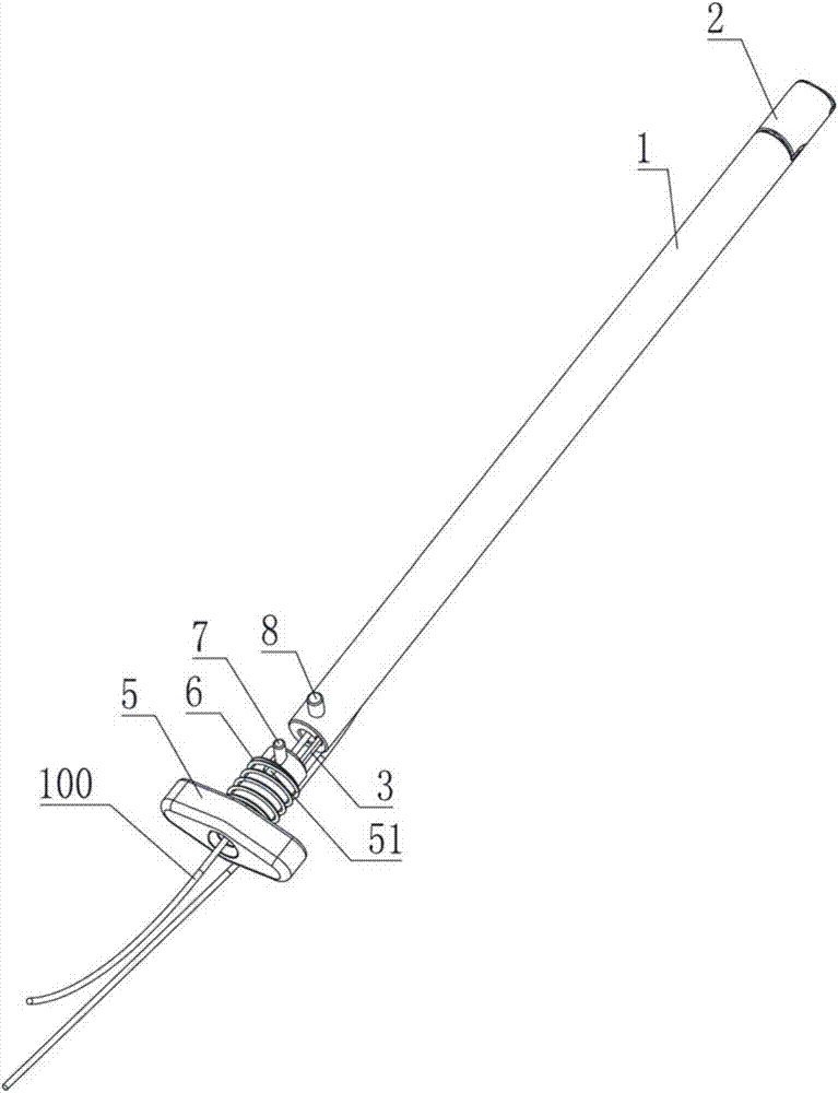
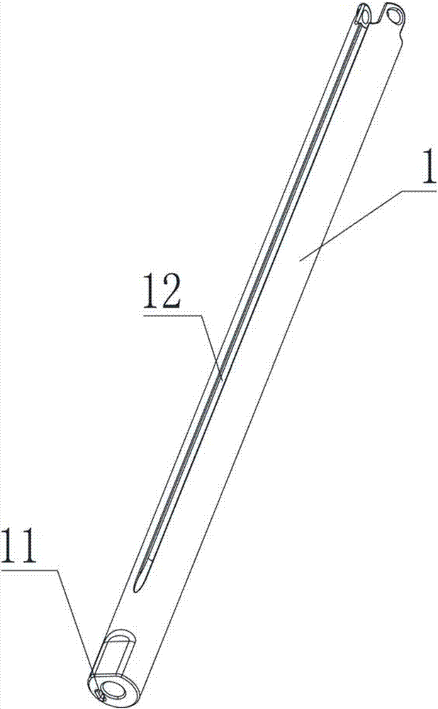
[0038] like Figure 1-Figure 3 As shown, the arthroscopic posterior cruciate ligament reconstruction tibial tunnel traction wire guide sleeve provided by the embodiment of the present invention includes a wire-passing sleeve 1, a hinged section 2 and a first push rod 3, wherein the hinged section 2 and the wire-passed sleeve The pipe 1 is hinged and can rotate relative to the wire-passing sleeve 1. The pipe wall of the wire-passing sleeve 1 is provided with a first push rod groove 11 arranged along the axial direction of the wire-passing sleeve 1, and one end of the first push rod 3 extends into the The first push rod slot 11 is capable of moving along the first push rod slot 11 , and the angle of rotation of the hinge section 2 relative to the wire-passing sleeve 1 is adjusted by using the length protruding from the first push rod slot 11 .

[0039] like figure 1 and Figure 4 As shown, the hinged section 2 is a hollow tube structure as a whole, and one end of the hinged se...

Embodiment 2

[0054] Such as Figure 7-Figure 11 As shown, the second embodiment is basically the same as the first embodiment, and the similarities will not be repeated. The difference is that the arthroscopic posterior cruciate ligament reconstruction tibial tunnel traction wire guide sleeve of this embodiment also includes a hinged transition section 9 and the second push rod 10, the hinged transition section 9 is a hollow tube structure, one end of which is hinged with the wire sleeve 1, and the other end is hinged with the hinged section 2, that is, the hinged transition section 9 is connected with the wire sleeve 1 and the hinged section at the same time. 2 hinged. A third push rod groove 91 corresponding to the first push rod groove 11 is provided on the hinged transition section 9. In an unbent state, the first push rod 11 passes through the first push rod groove 11 and the third push rod groove 11 in turn. Rod groove 91, when pushed forward, can be pressed against the hinged secti...


PUM

PropertyMeasurementUnit
Lengthaaaaaaaaaa
Lengthaaaaaaaaaa

Abstract

The invention relates to the technical field of medical instruments, in particular to a tibial tunnel traction suture guide cannula for arthroscopic posterior cruciate ligament reconstruction. The traction suture guide cannula comprises a suture-crossing cannula, a hinge section and a first push rod, a first push rod groove is formed in the cannula wall of the suture-crossing cannula in the axialdirection of the suture-crossing cannula, and the hinge section is of a hollow tube structure; one end of the hinge section is hinged to the suture-crossing cannula, the outer end of the hinge sectionis provided with a traction suture reversing shaft, and the first push rod movably extends into the first push rod groove to push the hinge section to rotate relative to the suture-crossing cannula so that a traction suture can go from the front portion of a tibial tunnel to the rear portion of the tibial tunnel and then return to the front portion of a knee joint; the traction suture can be quickly drawn out of the tibial tunnel just by gently peeling off an articular capsule at a posterior cruciate ligament attachment part instead of forming posterior inner-side or posterolateral incisionsin a whole operation, the operational procedures are effectively simplified, the risk of vascular nerve injuries behind the knee joint is greatly reduced, and the operation time is saved.

Description

technical field [0001] The invention relates to the technical field of medical devices, in particular to a traction wire guiding sleeve for posterior cruciate ligament reconstruction under arthroscopy. Background technique [0002] The rupture of the posterior cruciate ligament of the knee is a common type of knee injury. At present, the use of arthroscopy to reconstruct the PCL (the posterior cruciate ligament of the knee) has become the most ideal choice. One of the difficulties in the operation is to pull the ligament traction line from the front of the tibial tunnel Send to the back of the tibial tunnel, and then turn back to the front of the knee joint. However, since the posterior cruciate ligament is located behind the knee joint and adjacent to the blood vessels and nerves of the popliteal fossa, and because the tibial insertion of the posterior cruciate ligament is covered by soft tissue, the operation needs to be guided from the tibial tunnel under direct vision th...

Claims


Application Information

Patent Timeline
IPC IPC(8): A61B17/34
CPCA61B17/3468A61B2017/3454
Inventor 王少杰夏春
Owner ZHONGSHAN HOSPITAL XIAMEN UNIV
Why Eureka
Try Eureka