Directly operable clutch with vented geometry

A technology of clutch and clutch disc, applied in the direction of clutch, friction clutch, mechanical drive clutch, etc., to achieve the effect of increased cooling performance, simplified manufacturing and low cost

Active Publication Date: 2018-11-06
SCHAEFFLER TECH AG & CO KG
View PDF10 Cites 0 Cited by
  • Summary
  • Abstract
  • Description
  • Claims
  • Application Information

AI Technical Summary

Problems solved by technology

Furthermore, it has proven to be disadvantageous with the known disc springs that they change their tilted position when pivoting from the engaged position into the disengaged position.

Method used


Image

  • Directly operable clutch with vented geometry
  • Directly operable clutch with vented geometry
  • Directly operable clutch with vented geometry

Examples


Embodiment Construction

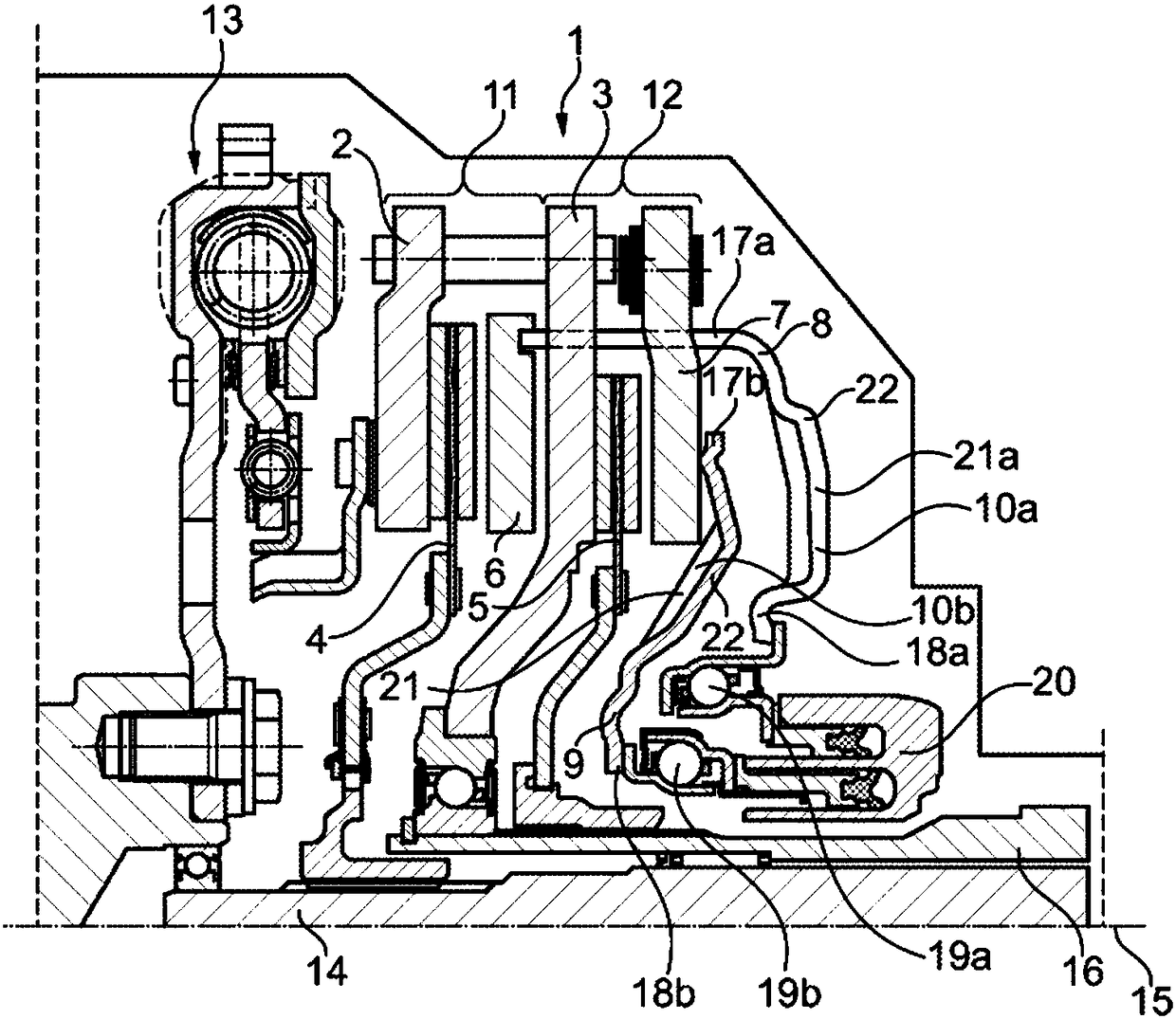
[0029] exist figure 1A first embodiment of a friction clutch 1 (also referred to as friction coupling) according to the invention can be seen in FIG. The friction clutch 1 is designed for a drive train of a motor vehicle, such as a Passenger cars, trucks, buses or agricultural trucks. The friction clutch 1 is designed here as a dry friction clutch 1 , as an alternative thereto, it can also be designed as a wet friction clutch 1 . The friction clutch 1 is also designed and used as a double clutch, as is basically known from DE 10 2011 013 475 A1. The disclosure content of DE 10 2011 013 475 A1 is therefore incorporated here.

[0030] The friction clutch 1 basically has pressure plates 6 , 7 which can be moved back and forth relative to the counter pressure plates 2 , 3 and the clutch plates 4 , 5 in order to engage and disengage the clutch 1 . Furthermore, the friction clutch 1 also has actuating elements 8 , 9 which influence the displacement position of the pressure plate...


PUM


Abstract

The present invention relates to a friction clutch for a power train of a motor vehicle, said friction clutch having: a pressure plate movable relative to a counter pressure plate and a clutch disc to engage and disengage the clutch; and an operating element, said An actuating element which influences the displacement position of the pressure plate is connected to the pressure plate in a rotationally fixed manner, the actuating element having at least one fluid deflection section which, in the operating state of the clutch, guides a cooling fluid into the interior of the clutch In order to cool the pressure plate, the counter pressure plate and / or the clutch disk, wherein the actuating element is designed as a rigid component, and the invention relates to a system consisting of such a friction clutch and a transmission cover.

Description

technical field [0001] The invention relates to a (preferably directly actuated) friction clutch / friction coupling for a drive train of a motor vehicle, for example a passenger car, a truck, a bus or an agricultural truck, The friction clutch / friction coupling has a pressure plate which is displaceable relative to a counter pressure plate and a clutch plate in order to engage and disengage the friction clutch; The actuating element has at least one fluid deflection section which, in the operating state of the clutch, guides cooling fluid into the interior of the clutch in order to generate (and / or intensify) a cooling fluid flow within the clutch in order to Cool pressure plate, counter pressure plate and / or clutch disc. Background technique [0002] Directly actuated clutches, for example directly actuated double clutches, are already known from the prior art. For example, DE 10 2011 013 475 A1 discloses a double clutch with a first and a second spring element, wherein th...

Claims


Application Information

Patent Timeline
Patent Type & Authority Patents(China)
IPC IPC(8): F16D13/72
CPCF16D13/72F16D13/70F16D2300/0212F16D2021/0615F16D2021/0669F16D25/10F16D25/082F16D25/08F16D13/385F16D2200/0004F16D2250/0023F16D2300/22
Inventor 勒内·赫尔格特勒内·代克勒
Owner SCHAEFFLER TECH AG & CO KG
Why Eureka
Try Eureka