Method and device for heating a connection element

A technology for connecting elements and components, applied in the field of heating connecting elements, can solve the problems of unutilized output of heat energy, circuit damage, etc.

Active Publication Date: 2020-10-30
BDTRONIC
View PDF7 Cites 0 Cited by
  • Summary
  • Abstract
  • Description
  • Claims
  • Application Information

AI Technical Summary

Problems solved by technology

Especially sensitive components such as electrical circuits may be irreversibly damaged by high heat
Another disadvantage of the aforementioned method is that most of the thermal energy is exported unused to the surrounding environment

Method used


Image

  • Method and device for heating a connection element
  • Method and device for heating a connection element
  • Method and device for heating a connection element

Examples


Embodiment Construction

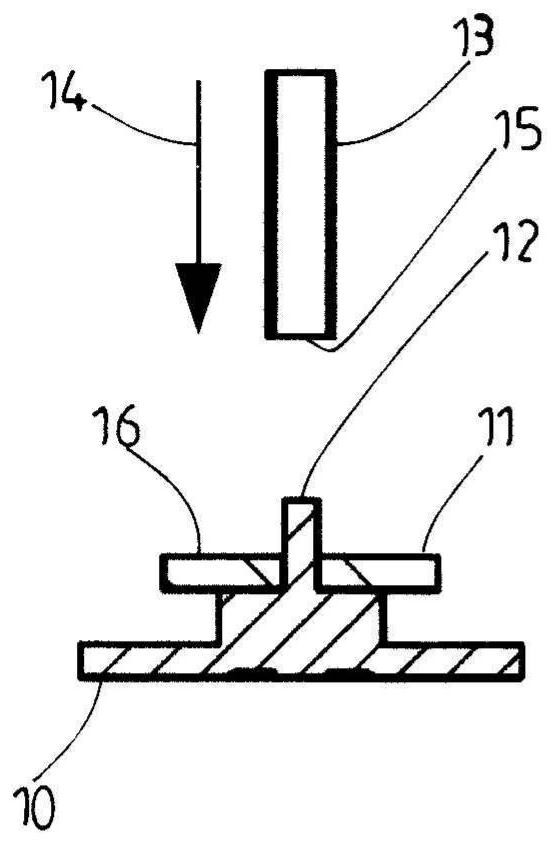
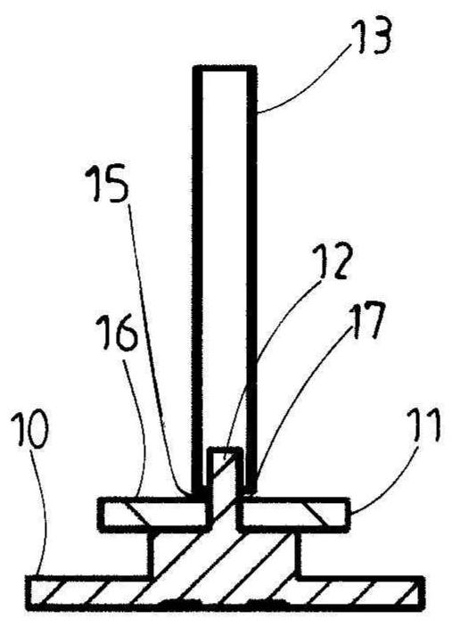
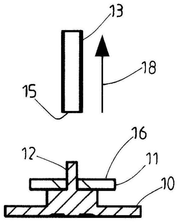
[0030] In order to connect the first part 10 with the second part 11 (also called joint partner), it is known to first heat the connecting element 12 (also called pin or rivet) by applying a heat medium or hot air ( Figure 1a , 1b, 1c). In this example representing prior art, the connecting element 12 is an integral part of the first part 10 and is guided through an opening in the second part 11 . Here, the substantially tubular nozzle 13 is first guided in the direction of the arrow 14 over the connecting element 12 ( Figure 1a , 1b ). For the sake of clarity, only a strongly schematic part of the nozzle 13 is shown here. It goes without saying that connecting elements 12 can also be supplied to the nozzle.

[0031] The hot air to be guided through the nozzles 13 is generated by a not shown hot air generator. In this case, air is first supplied to the hot air generator and subsequently heated to the desired temperature. The hot air is guided through the nozzles 13 dir...


PUM


Abstract

Riveting two parts together is a known method for connecting two parts. Hot air is used to make the plastic connection element deformable in the thermo-riveting of parts made of plastic. In this method, it is inevitable that other parts are also supplied with thermal energy, which can lead to unwanted damage. The invention provides a device and a method in which this disadvantage is eliminated. This is achieved in that a sleeve (19) is arranged around a hot air nozzle (13) and an at least approximately annular channel (20) is formed between an outer wall of the nozzle (13) and an inner wall ofthe sleeve (19) in order to extract the hot air.

Description

technical field [0001] The invention relates to a device for heating connecting elements according to the preamble of claim 1 . Furthermore, the invention relates to a method for heating a connecting element according to the preamble of claim 10 . Background technique [0002] In order to connect two parts to one another, it is known to rivet the two parts to one another. In this case, for example, the first part and the second part, or the joining partners, are brought into contact and then fixedly connected to one another by connecting means or by rivets or pins. [0003] In the heat riveting of parts made of plastic, a heat medium, such as hot air, is used to heat and deform the connecting element made of plastic so that the forming punch can deform the connecting element for joining two part. Nozzles are used to load the connecting elements with heat medium. The nozzle is, for example, tubular in design and is dimensioned such that it can be guided with an end region...

Claims


Application Information

Patent Timeline
Patent Type & Authority Applications(China)
IPC IPC(8): B29C65/10B29C65/60B21J15/08
CPCB29C65/10B29C65/606B29C66/003B29C66/0242B29C66/1122B29C66/21B29C66/348B29C66/41B29C66/8167B29C66/8322B29C66/872B29C66/9672
Inventor C·赫尔曼A·加赫斯特I·雷米格T·克拉夫特
Owner BDTRONIC
Why Eureka
Try Eureka