Al technical title is built by PatSnap Al team. It summarizes the technical point description of the patent document.
A technology of cutting device and double cutter, applied in shearing device, positioning device, feeding device, etc., can solve the problems of different rotation speed, single specification, low efficiency, etc., and achieve the effect of ensuring sharpness, stable plate, and saving trouble.
Active Publication Date: 2018-04-06
宣城大天新材料科技股份有限公司
View PDF7 Cites 17 Cited by
Summary
Abstract
Description
Claims
Application Information
AI Technical Summary
This helps you quickly interpret patents by identifying the three key elements:
Problems solved by technology
Method used
Benefits of technology
Problems solved by technology
[0003] Some boards are often used in packaging. At present, the commonly used boards include wood boards, cardboards, metal boards and plastic boards. However, no matter what kind of boards are actually produced, it is impossible to say that they are of a single specification. In the actual use process, it is still necessary. For processing, the most commonly used processing equipment is the cutting machine. As the name suggests, the cutting machine is the equipment used for cutting. Most of the existing plate cutting machines use a single cutting wheel to achieve cutting. This kind of cutting machine needs to be used when cutting plates. It is inefficient to draw a line on the plate, although there are cutting machines with double cutting wheels, but these cutting machines are driven by dual power, which requires two controllers, and the dual power drives are different. The cutting wheel will have two cutting wheels with different rotation speeds, which will cause the cutting surface to be uneven during cutting, so it needs to be improved
Method used
Image
Click on the blue label to locate the original text in one second.
Reading with bidirectional positioning of images and text.
Examples
Embodiment Construction
[0020] The technical solution of the present patent will be described in further detail below in conjunction with specific embodiments.
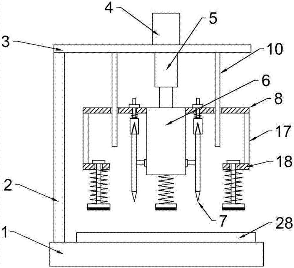
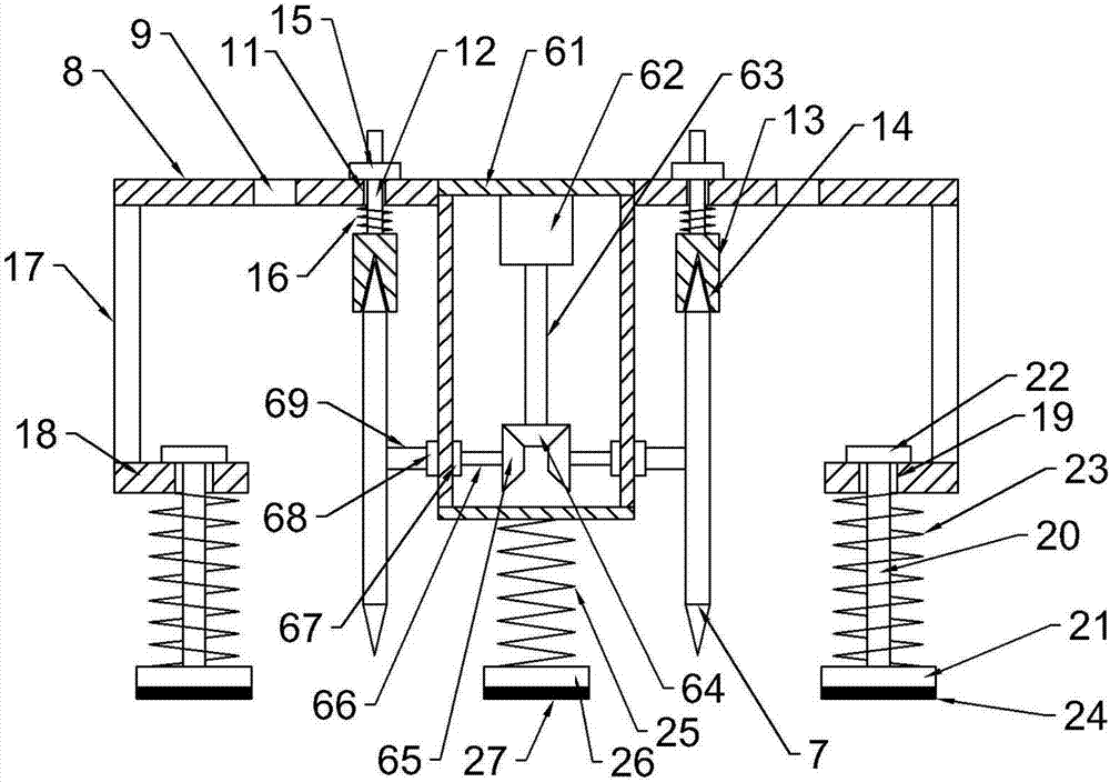
[0021] see Figure 1-4 , a double-cutter cutting device for packaging plates, comprising a base 1, a support column 2 is installed on the left side of the upper end of the base 1, a horizontal plate 3 is installed on the top of the support column 2, and a first center is installed on the upper end of the horizontal plate 3. The motor 4, the lower end of the first motor 4 is connected with a feeding mechanism 5, the feeding mechanism 5 is arranged below the horizontal plate 3, and the lower end of the feeding mechanism 5 is installed with a cutting mechanism 6, the cutting mechanism 6 includes a casing 61, the casing The outer wall of the upper end of the 61 is connected with the feeding mechanism 5, a second motor 62 is installed on the inner top wall of the housing 61, the west section of the second motor 62 is connected with a drive shaft ...
PUM
Abstract
The invention discloses a double-cutter cutting device for packing plates. The double-cutter cutting device comprises a base, a supporting column, a transverse plate, a first motor, a feed mechanism,a cutting mechanism and an extension plate, and the cutting mechanism comprises a shell, a second motor, a driving shaft, a driving bevel gear, a driven bevel gear, a rotating shaft, a coupling and aconnecting shaft; cutting wheels are mounted at the end, away from the coupling, of the connecting shaft, and mounting holes are formed in the side, close to the shell, on the extension plate; threaded columns are arranged in the mounting holes, and friction blocks are mounted at the lower ends of the threaded columns; and a first spring is further arranged on each threaded column in a sleeving mode, and the first springs are located between the extension plate and the friction blocks. According to the double-cutter cutting device for the packing plates, single power is adopted to drive the double cutting wheels, the same rotational speed of the two cutting wheels can be achieved, neat cutting is ensured, by arranging the friction blocks, the cutting wheels can be grinded while being cut,so that the cutting wheels is ensured to be sharp, the plates can be pressed and fixed while feeding of the cutting mechanism is conducted by arranging pressing blocks, and a separate control fixtureis not required to be arranged.
Description
technical field [0001] The invention relates to a packaging board processing equipment, in particular to a packaging board double cutter cutting device. Background technique [0002] Packaging is the general name of containers, materials and auxiliary materials used in accordance with certain technical methods to protect products in the process of circulation, facilitate storage and transportation, and promote sales; it also refers to the process of using containers, materials and auxiliary materials for the above purposes. Operational activities in which certain technical methods are applied. Marketing-oriented packaging focuses on planning strategies and becomes a generalized packaging. You can also dress up someone or something or try to help him be perfect in some way. [0003] Some boards are often used in packaging. Currently, commonly used boards include wood, cardboard, metal and plastic boards, but no matter which board is actually produced, it is impossible to sa...
Claims
Application Information
Patent Timeline
Application Date:The date an application was filed.
Publication Date:The date a patent or application was officially published.
First Publication Date:The earliest publication date of a patent with the same application number.
Issue Date:Publication date of the patent grant document.
PCT Entry Date:The Entry date of PCT National Phase.
Estimated Expiry Date:The statutory expiry date of a patent right according to the Patent Law, and it is the longest term of protection that the patent right can achieve without the termination of the patent right due to other reasons(Term extension factor has been taken into account ).
Invalid Date:Actual expiry date is based on effective date or publication date of legal transaction data of invalid patent.