Sealing ring suitable for shaft with high rotating speed and large run-out amount
A sealing ring and runout technology, which is applied to the sealing of the engine, engine components, mechanical equipment, etc., can solve the problem of low followability, achieve the effects of long product life, stable and reliable sealing, and improved followability
- Summary
- Abstract
- Description
- Claims
- Application Information
AI Technical Summary
Problems solved by technology
Method used
Image

Examples
no. 1 example
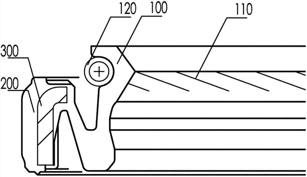
[0023] refer to figure 2 The schematic diagram of the first embodiment of the shaft sealing ring is shown, and the present invention proposes a shaft sealing ring suitable for high speed and large runout. The shaft sealing ring includes: an oil return line 110, which is arranged inside the lip 100 of the shaft sealing ring; a support part 200 with a "Z" shape structure connected to the lip 100 of the shaft sealing ring; a metal skeleton 300 , which is completely covered by the support part 200; and a radial force compensation spring 400, which is arranged outside the lip 100 of the shaft sealing ring.
[0024] In this embodiment, the metal skeleton 300 is at the end of the supporting part 200 away from the lip 100 . The supporting part 200 is made of elastic material. A pressure sensor 500 is disposed outside the support portion 200 . The pressure sensor 500 is connected to an external indicator light 600 . When the supporting part 200 falls off due to misalignment with t...
no. 2 example
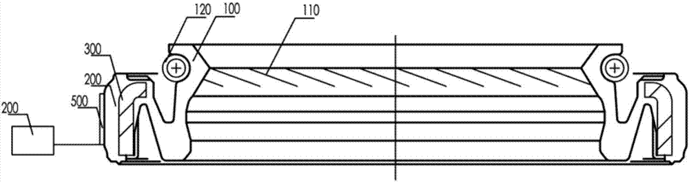
[0026] refer to image 3 The schematic diagram of the second embodiment of the shaft sealing ring is shown, and the present invention proposes a shaft sealing ring suitable for high speed and large runout. The shaft sealing ring includes: an oil return line 110, which is arranged inside the lip 100 of the shaft sealing ring; a support part 200 with a "Z" shape structure connected to the lip 100 of the shaft sealing ring; a metal skeleton 300 , which is completely covered by the support part 200; and a radial force compensation spring 400, which is arranged outside the lip 100 of the shaft sealing ring.
[0027] In this embodiment, the metal skeleton 300 is at the end of the supporting part 200 away from the lip 100 . The supporting part 200 is made of elastic material. The aforementioned elastic material is preferably KFM rubber (fluororubber). Preferably, the cross-section of the metal skeleton is an "L"-shaped structure, so as to improve the followability of the lip 100 t...
no. 3 example
[0029] refer to Figure 4 The schematic diagram of the third embodiment of the shaft sealing ring is shown. The present invention proposes a shaft sealing ring suitable for high speed and large runout. The shaft sealing ring includes: an oil return line 110, which is arranged inside the lip 100 of the shaft sealing ring; a support part 200 with a "Z" shape structure connected to the lip 100 of the shaft sealing ring; a metal skeleton 300 , which is completely covered by the support part 200; and a radial force compensation spring 400, which is arranged outside the lip 100 of the shaft sealing ring.
[0030] In this embodiment, the metal skeleton 300 is at the end of the supporting part 200 away from the lip 100 . The supporting part 200 is made of elastic material. The aforementioned elastic material is preferably KFM rubber. A pressure sensor 500 is disposed outside the support portion 200 . The pressure sensor 500 is connected to an external indicator light 600 . When t...
PUM
 Abstract
Description
Claims
Application Information
 - R&D Engineer
- R&D Manager
- IP Professional
- Industry Leading Data Capabilities
- Powerful AI technology
- Patent DNA Extraction
Browse by: Latest US Patents, China's latest patents, Technical Efficacy Thesaurus, Application Domain, Technology Topic.
© 2024 PatSnap. All rights reserved.Legal|Privacy policy|Modern Slavery Act Transparency Statement|Sitemap