Sealing structure

A technology of sealing structure and sealing parts, which is applied in the direction of engine sealing, mechanical equipment, engine components, etc. It can solve the problems of high resilience of fluorinated resin, reduced sealing effect, and particle drop, so as to improve sealing performance and prolong service life Life, effect of preventing backlash

Pending Publication Date: 2022-05-20
NIDEC SANKYO (ZHEJIANG) CORPORATION +1
View PDF0 Cites 0 Cited by
  • Summary
  • Abstract
  • Description
  • Claims
  • Application Information

AI Technical Summary

Problems solved by technology

[0003] However, although friction at the screw-fastened portion can be suppressed by introducing a seal 4' such as fluorinated rubber between the robot arm 1' and the dust cover 3', the followability is low due to the high resilience of the fluorinated resin. , so when the mechanical arm 1' moves, due to the deformation of the mechanical arm 1', a gap G will be generated between the seal 4' and the mechanical arm 1' ( figure 1 The gap G in is shown enlarged for illustration only, and does not represent the actual size), thereby reducing the sealing effect and causing problems such as particle falling at the gap G

Method used


Image

  • Sealing structure
  • Sealing structure

Examples


Embodiment Construction

[0042] Reference will now be made in detail to various embodiments of the present invention, examples of which are illustrated in the accompanying drawings and described below. While the invention will be described in conjunction with exemplary embodiments, it will be appreciated that present description is not intended to limit the invention to those exemplary embodiments. On the contrary, the invention is intended to cover not only the exemplary embodiments but also various alternatives, modifications, equivalents and alternatives, modifications, equivalents and various alternatives, modifications, equivalents and other implementations. For ease of explanation and precise definition in the appended claims, the terms "upper", "lower", "inner" and "outer" are used to refer to the positions of features of the exemplary embodiments as shown in the drawings. characteristics are described.

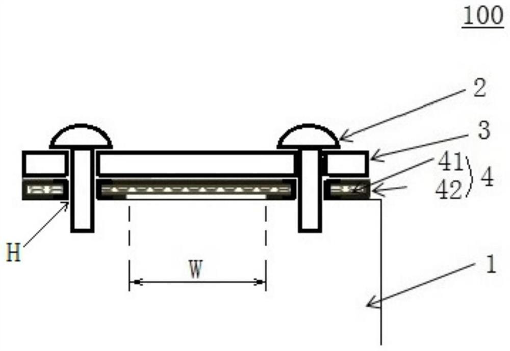
[0043] Such as figure 2 As shown, the sealing structure 100 of this embodiment include...


PUM


Abstract

A sealing structure includes: a mechanical arm of a robot; the dustproof cover covers the mechanical arm and is fastened on the mechanical arm through a fastener; the sealing piece is clamped between the mechanical arm and the dustproof cover, and comprises a low-resilience material, an elastic material and an elastic material; and a film surrounding at least the outer peripheral surface of the low-resilience material. According to the sealing structure provided by the invention, the sealing performance between the mechanical arm and the dustproof cover can be ensured even when the mechanical arm of the robot acts.

Description

technical field [0001] The invention relates to a sealing structure, in particular to a sealing structure for a robot. Background technique [0002] Such as figure 1 As shown, in a robot used for handling large-sized workpieces such as liquid crystal panels, a dust cover 3' made of aluminum or the like is usually covered on the hollowed-out mechanical arm 1' of the robot by fastening screws 2' to prevent The mechanical arm 1' is scratched by the workpiece, etc., while preventing dust and the like from entering the hollowed-out internal space of the mechanical arm 1'. In addition, in the prior art, a sealing member 4' such as fluorinated rubber is usually sandwiched between the mechanical arm 1' and the dust cover 3' to further improve the dustproof effect, and at the same time protect the parts where the screws are fastened . [0003] However, although the friction at the screw-fastened part can be suppressed by introducing a seal 4' such as fluorinated rubber between the...

Claims


Application Information

Patent Timeline
IPC IPC(8): F16J15/10
CPCF16J15/102
Inventor 王卿矢泽隆之田边智树
Owner NIDEC SANKYO (ZHEJIANG) CORPORATION
Why Eureka
Try Eureka