
Pantograph for rail transit

A technology for rail transit and pantographs, applied in collectors, electric vehicles, power collectors, etc., can solve the problems of pantograph followability and poor current receiving stability, and achieve improved current receiving stability and followability , good mechanical properties

Pending Publication Date: 2020-09-15
成都永贵东洋轨道交通装备有限公司
View PDF1 Cites 1 Cited by
  • Summary
  • Abstract
  • Description
  • Claims
  • Application Information

AI Technical Summary

Problems solved by technology

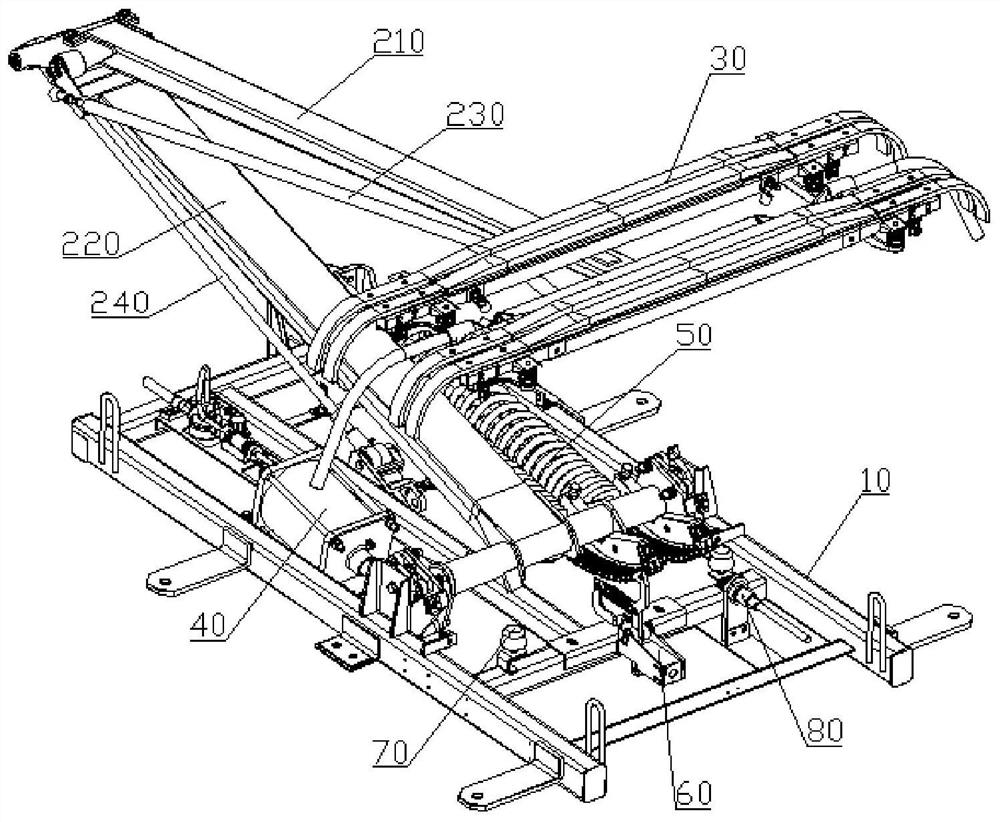
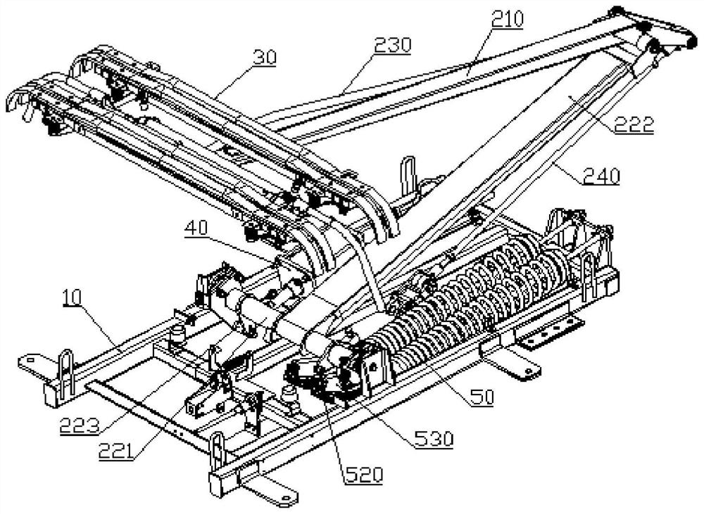
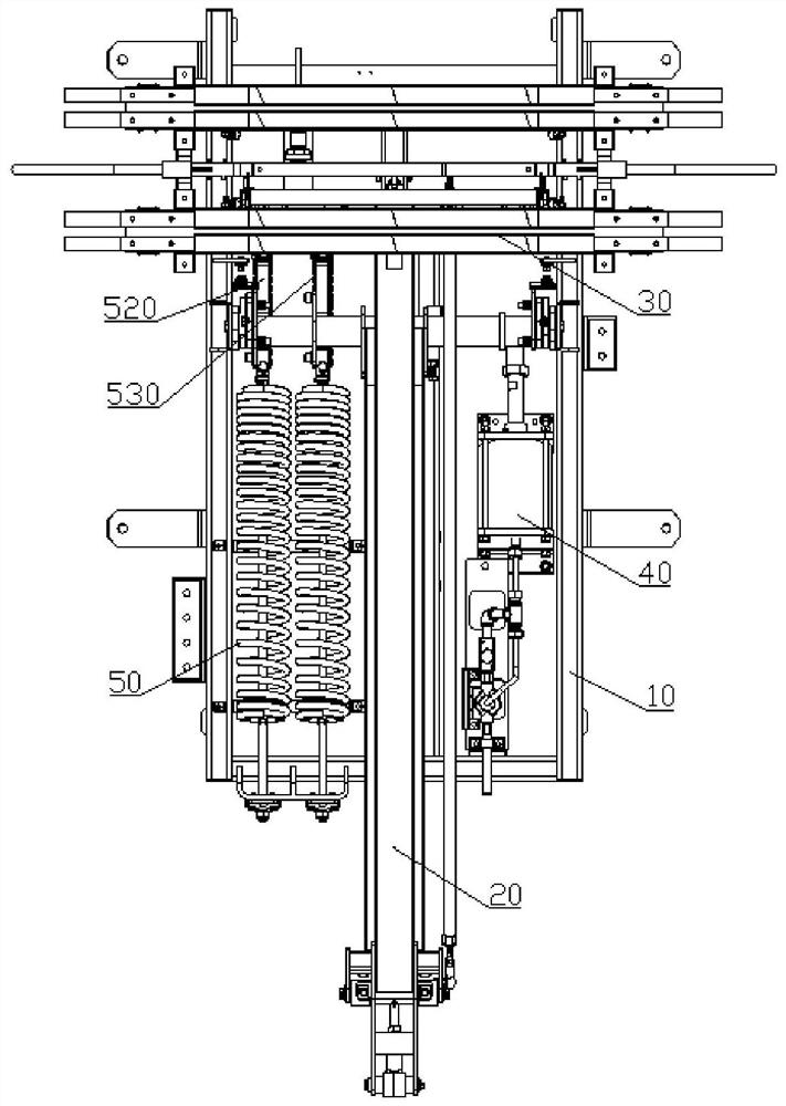
[0005] The purpose of the present invention is to provide a pantograph for rail transit in view of the poor followability and current receiving stability of the existing pantograph, which uses an airbag spring and a guide device to cooperate in the bow head structure to improve The current receiving stability and followability of the bow head after being impacted, the spring lifting device is used to provide the bow lifting force, no air source is needed during operation, and the cushioning performance of the lifting arm is maintained, which further improves the current receiving stability and performance of the pantograph following

Method used


Image

  • Pantograph for rail transit
  • Pantograph for rail transit
  • Pantograph for rail transit

Examples


Embodiment Construction

[0029] Below in conjunction with accompanying drawing, the present invention is described in detail.

[0030] In order to make the object, technical solution and advantages of the present invention clearer, the present invention will be further described in detail below in conjunction with the accompanying drawings and embodiments. It should be understood that the specific embodiments described here are only used to explain the present invention, not to limit the present invention.

[0031] refer to Figure 1 to Figure 11 The rail transit pantograph disclosed according to this embodiment includes a base 10, a lifting arm 20 and a micro-moving bow head 30, the upper end of the lifting arm 20 is connected to the micro-moving bow head 30, and the central shaft 221 at the lower end of the lifting arm 20 Installed on the base 10 , a spring bow raising device 50 and a bow lowering device 40 are arranged between the central rotating shaft 221 and the base 10 to drive the central rot...


PUM


Abstract

The invention discloses a pantograph for rail transit, and relates to the technical field of pantographs of electric vehicles. The pantograph comprises a base, a lifting arm and a pantograph head. Anupper end of the lifting arm is connected with a micro-motion pantograph head, a central rotating shaft at a lower end of the lifting arm is rotatably mounted on the base, and a spring pantograph lifting device and a spring pantograph lowering device for driving the central rotating shaft to rotate are arranged between the central rotating shaft and the base; and the micro-motion pantograph head comprises a pantograph head support, an air bag spring and a carbon sliding plate assembly, the carbon sliding plate assembly is installed on the pantograph head support through the air bag spring, anda guide device for guiding a lifting direction of the carbon sliding plate assembly is arranged between the pantograph head support and the carbon sliding plate assembly. The air bag spring and the guide device are used in the pantograph head structure for cooperation, the spring pantograph lifting device is used for providing a pantograph lifting force, an air source is not needed in an operation process, and buffering performance, current collection stability and following performance of the pantograph head and the lifting arm are improved.

Description

technical field [0001] The invention relates to the technical field of pantographs for electric vehicles, in particular to pantographs for rail transit. Background technique [0002] Urban rail vehicles for urban use mainly include subways, light rails or trams. When the vehicles are running, they rely on the pantograph with the raised roof to contact the catenary to supply power to the vehicles. The pantograph head is an important part of the pantograph. The bow head is the part on the pantograph that is in contact with the catenary. Its working conditions are harsh, and its performance directly determines the current quality and reliability of the pantograph. . [0003] The Chinese invention patent with the application number 201120097224.0 discloses a pantograph for trunk line locomotives, which controls the raising and lowering of the pantograph through a double-airbag raising device. Its double-airbag bow-raising device includes connecting plate, steel wire rope assem...

Claims


Application Information

Patent Timeline
IPC IPC(8): B60L5/20B60L5/30
CPCB60L5/205B60L5/30
Inventor 巴永林山田浩二纪刚孔祥斌
Owner 成都永贵东洋轨道交通装备有限公司
Learn More