A Calibration Method for Circular Structured Light

A technology of circular structured light and calibration method, which is applied in the direction of using optical devices, instruments, measuring devices, etc., can solve the problems of high operational difficulty, need, and ignoring assembly errors, etc., and achieve low experimental cost, simple operation, and easy realization. Effect

Active Publication Date: 2020-01-03
UNIV OF SCI & TECH OF CHINA
View PDF1 Cites 0 Cited by
  • Summary
  • Abstract
  • Description
  • Claims
  • Application Information

AI Technical Summary

Problems solved by technology

This method requires additional standard ring gauges, increasing the cost of the experimental setup
Moreover, it is required that the centerline of the ring gauge and the centerline of the circular structured light are absolutely coincident, and the experimental operation is very difficult.
[0007] 4. Albertazzi et al. also used the standard cylinder to move along the precise axis to calibrate the circular structured light equation, which also has the same disadvantages
Wang uses a concentric circle calibration plate to calibrate the detector based on cross-ratio invariance. This method requires the calibration plate to move precisely along the circular structured light axis, which is difficult to operate and requires a precise moving device.
[0008] 5. Wakayama et al. calibrated the detector parameters through precise processing and assembly, and this method did not consider assembly errors, but assembly errors often have to be considered
[0009] 6. Zhu et al. successfully calibrated the parameters of circular structured light with an auxiliary camera. This method is easy to operate, but this method requires an additional auxiliary camera, which increases the cost of the experiment

Method used


Image

  • A Calibration Method for Circular Structured Light
  • A Calibration Method for Circular Structured Light
  • A Calibration Method for Circular Structured Light

Examples


Embodiment Construction

[0026] The following describes the technical solutions in the embodiments of the present invention clearly and completely with reference to the accompanying drawings in the embodiments of the present invention. Obviously, the described embodiments are only a part of the embodiments of the present invention, rather than all the embodiments. Based on the embodiments of the present invention, all other embodiments obtained by those of ordinary skill in the art without creative work shall fall within the protection scope of the present invention.

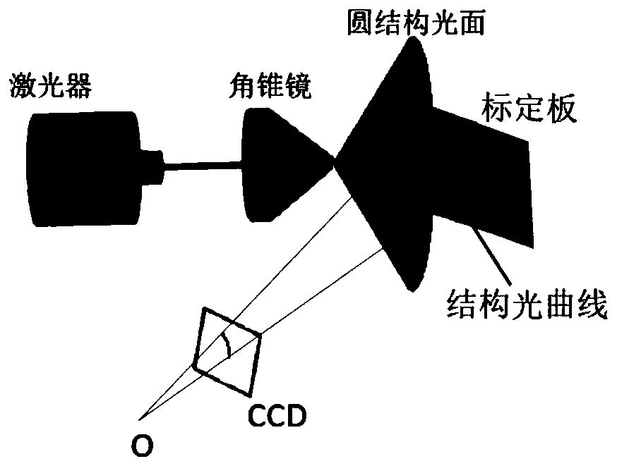
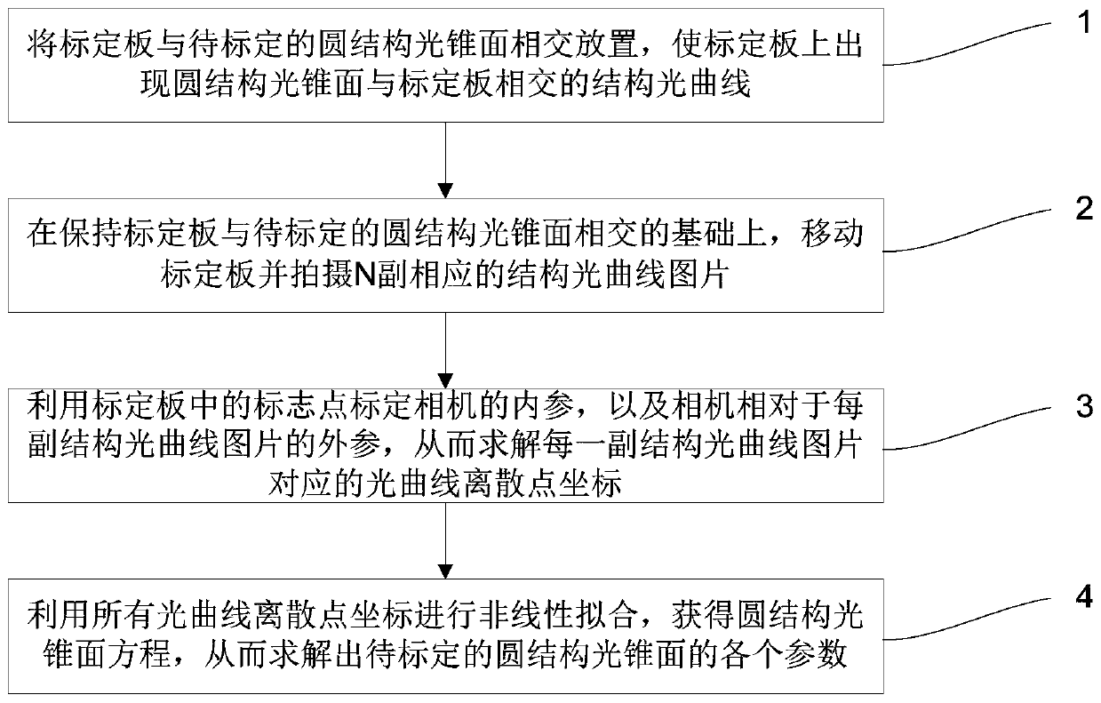
[0027] The embodiment of the present invention provides a method for calibrating circular structured light, the principle of which can be referred to figure 1 , The overall idea of ​​this method is: place the calibration plate and the circular structure light cone intersectingly. At this time, a structured light curve with a circular structured light cone intersecting the calibration plate will appear on the calibration plate. The camera t...


PUM


Abstract

The invention discloses a calibration method for circular structured light. The method comprises steps that a calibration plate and a to-be-calibrated circular structured light cone surface are arranged in an intersected mode, and a structured light curve generated because of intersection of the circular structured light cone surface and the calibration plate is made to appear on the calibration plate; on the basis of maintaining intersection of the calibration plate and the to-be-calibrated circular structured light cone surface, moving the calibration plate, N corresponding structured lightcurve pictures are shot; mark points of the calibration plate are utilized to calibrate internal parameters of the camera and external parameters of the camera relative to each structured light curvepicture, and a light curve discrete point coordinate corresponding to each structured light curve picture is solved; all the light curve discrete point coordinates are utilized to carry out non-linearfitting to acquire a circular structured light cone surface equation, and each parameter of the to-be-calibrated circular structured light cone surface is solved. The method is advantaged in that therelated device structure is simple, the method is easy for realization, and cost is relatively low.

Description

Technical field [0001] The invention relates to the field of photogrammetry, in particular to a calibration method of circular structured light. Background technique [0002] The circular structured light detection system is widely used in scene reconstruction, inner wall damage detection and industrial measurement. One of the key technical issues is the calibration of structured light, that is, determining the expression equation of the circular structured light cone in the world coordinate system is extremely important. [0003] Currently, the following schemes are mainly used for structured light calibration: [0004] 1. Zhang Guangjun and others used the drawing method to calibrate the structured light. A thin line is used to intersect the linear structured smooth surface to generate a bright spot, and the three-dimensional position of the bright spot is determined by two electric theodolites, and the linear structured smooth surface equation is fitted by using these bright spo...

Claims


Application Information

Patent Timeline
Patent Type & Authority Patents(China)
IPC IPC(8): G01B11/00G01D18/00
CPCG01B11/00G01D18/00
Inventor 汪连坡朱烨翟超顾永刚
Owner UNIV OF SCI & TECH OF CHINA
Why Eureka
Try Eureka