
Mode switchable smart optical cable monitoring system and method

A switching mode and monitoring system technology, applied in the transmission system, electromagnetic wave transmission system, electrical components, etc., can solve the problems of low detection probability and high false alarm probability, achieve low false alarm probability, save optical fiber resources, and high optical cable breakpoint The effect of positioning accuracy

Inactive Publication Date: 2018-04-06
GUANGAN POWER SUPPLY COMPANY STATE GRID SICHUANELECTRIC POWER +1
View PDF5 Cites 9 Cited by
  • Summary
  • Abstract
  • Description
  • Claims
  • Application Information

AI Technical Summary

Problems solved by technology

[0004] The present invention solves the problem that the existing optical cable monitoring equipment cannot realize that the same RTU equipment is simultaneously compatible with the three working modes of fiber backup test, online test and protection monitoring, and provides an intelligent optical cable monitoring system with switchable modes, which can be used in addition to 24 hours All-weather real-time automatic monitoring of optical cable status; high detection probability, low false alarm probability and high optical cable breakpoint positioning accuracy; fast optical cable protection switching function; does not affect the normal operation of the original transmission system; has SMS , mail, sound and light and other alarm methods

Method used


Image

  • Mode switchable smart optical cable monitoring system and method
  • Mode switchable smart optical cable monitoring system and method
  • Mode switchable smart optical cable monitoring system and method

Examples


Embodiment

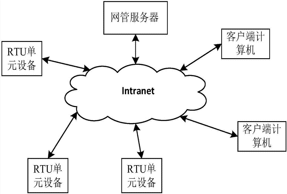
[0028] Such as figure 1 As shown, the intelligent optical cable monitoring system with switchable mode includes a light source module, a network management server, an RTU unit device and a client computer, the network management server is connected to the RTU unit device and the client computer respectively, and the RTU unit device is connected to the client computer The computer is connected, the quantity of described network management server is one, the quantity of described RTU unit equipment is several, the quantity of described client computer is several, described network management server and RTU unit equipment and client computer respectively through TCP / IP protocol connection, the RTU unit device is connected to the client computer through the TCP / IP protocol, wherein: the RTU unit device is used to complete the monitoring of the optical cable, obtain the monitoring curve and perform degradation analysis, and transmit the monitoring curve and degradation analysis res...


PUM


Abstract

The invention discloses a mode switchable smart optical cable monitoring system and method. The system comprises a light source module, a network management server, an RTU unit device and a client computer. According to the system and the method, the problem that an existing optical cable monitoring device cannot realize the fact that three working modes: a standby fiber test, an online test and protection monitoring are taken into consideration by the same RTU device at the same time is solved. The mode switchable smart optical cable monitoring system is provided. When the system is applied,24-hour all-whether real-time automatic monitoring can be carried out on an optical cable state; the system has a relatively high detection probability, a relatively low false alarm probability and the relatively high optical cable breakpoint positioning precision; the system has a rapid optical cable protection switching function; the normal operation of an original transmission system is not influenced; and the system has various alarm modes: a short message, a mail and sound and light. When the system is applied, the three working modes: the standby fiber test, the online test and the protection monitoring can be taken into consideration by the same RTU device at the same time. No matter which working mode is employed, an optical fiber in an optical cable is occupied, so optical fiber resources are greatly saved.

Description

technical field [0001] The invention relates to optical cable monitoring, in particular to an intelligent optical cable monitoring system and method with switchable modes. Background technique [0002] According to the "2015 Statistical Bulletin of the Communication Operation Industry" issued by the Ministry of Industry and Information Technology in early 2016, in 2015, 4.413 million kilometers of new optical cable lines were built nationwide, and the total length of optical cable lines reached 24.873 million kilometers. From 2010 to 2015, the growth rate of the total length of optical cable lines exceeded 20. %. Correspondingly, the maintenance tasks of the optical cable network will be more onerous. At present, the traditional optical cable maintenance method still mainly relies on manual labor, and basically follows the following process: fault occurs - notify the maintenance unit - drive to the fault site - test with OTDR - find the approximate location of the manhole -...

Claims


Application Information

Patent Timeline
IPC IPC(8): H04B10/071H04B10/079H04B10/032H04B10/038
CPCH04B10/071H04B10/032H04B10/038H04B10/07955
Inventor 李敏石同春秦少鹏蒋刚邓旭聪刘星岳欧罗宇昆李廷吴浩瀚龚玲玲李嘉懿唐鸿锐
Owner GUANGAN POWER SUPPLY COMPANY STATE GRID SICHUANELECTRIC POWER
Learn More