
Continuous web inline testing apparatus, defect mapping system and related methods

Inactive Publication Date: 2015-04-30
CELGARD LLC
View PDF8 Cites 20 Cited by
  • Summary
  • Abstract
  • Description
  • Claims
  • Application Information

AI Technical Summary

Benefits of technology

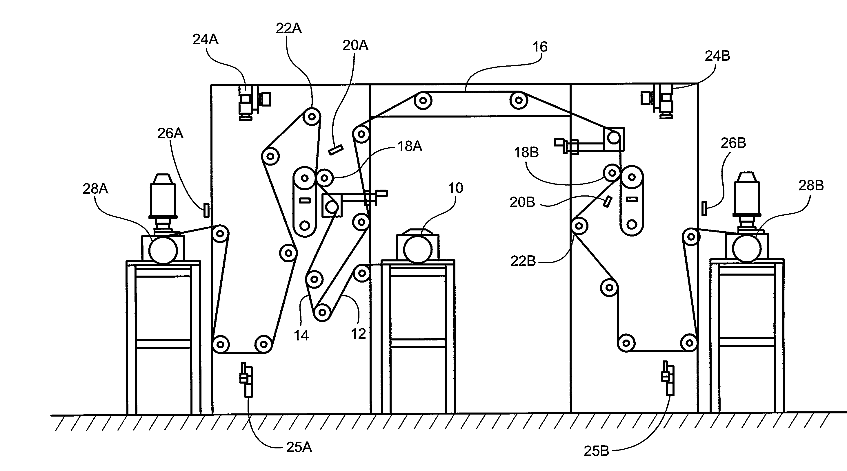
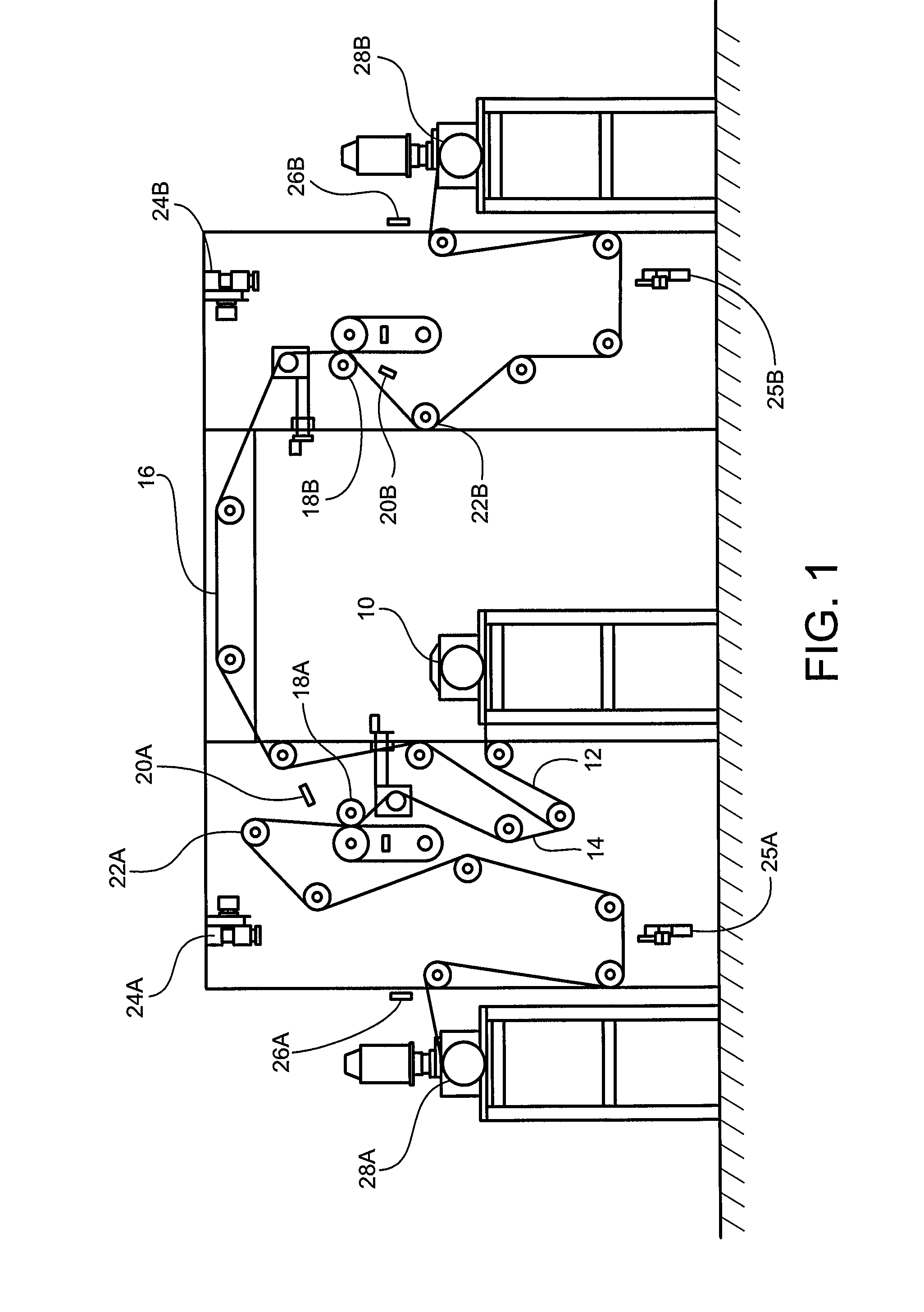
This patent describes a system for testing insulating material for the electronics and medical industries. It can detect defects like pinholes, weak spots, and conductive particles. The system was specifically designed for testing thin, microporous polymer membranes used in battery separators for rechargeable batteries. It can also inspect other non-conductive materials like medical wraps and packaging. The technology is versatile and can be used for a wide range of materials.

Problems solved by technology

The technology, although somewhat suitable for continuous web operation, is not 100% reliable to detect very small holes due to limited camera pixel resolution.
Also, cameras cannot detect weak, thin or damaged spots on the web that are not optically different.
Thus, various limitations exist related to using only an optical method (e.g., human eye observation only or camera only) for detecting defects in a continuous roll, sheet or web of material, since many defects, such as pinhole defects, may not be visible to a naked eye or standard optical camera.
“Hipot” as is known in the art is an abbreviation for “high potential.” Although there are one or more manufacturers making inline Hipot or pinhole testing equipment, the equipment is primitive, limited in use, and requires draping a metal beaded curtain over the moving web while applying the voltage.
The beaded curtain not only could damage sensitive web material, but also may not provide the desired coverage of the tested area.
Further, the metal beads themselves may become damaged or pitted on the surface due to high voltage shorts.
Additionally, prior art Hipot systems cannot map the defects in the moving web, and that makes current testing lose its main purpose, namely identifying defects to an operator so that decisions may be made, if any, regarding the continuous web or sheet material.

Method used


Image

  • Continuous web inline testing apparatus, defect mapping system and related methods
  • Continuous web inline testing apparatus, defect mapping system and related methods
  • Continuous web inline testing apparatus, defect mapping system and related methods

Examples


Embodiment Construction

[0011]At least certain selected embodiments of the instant invention are designed to at least address at least some of the above mentioned issues, needs and / or problems.

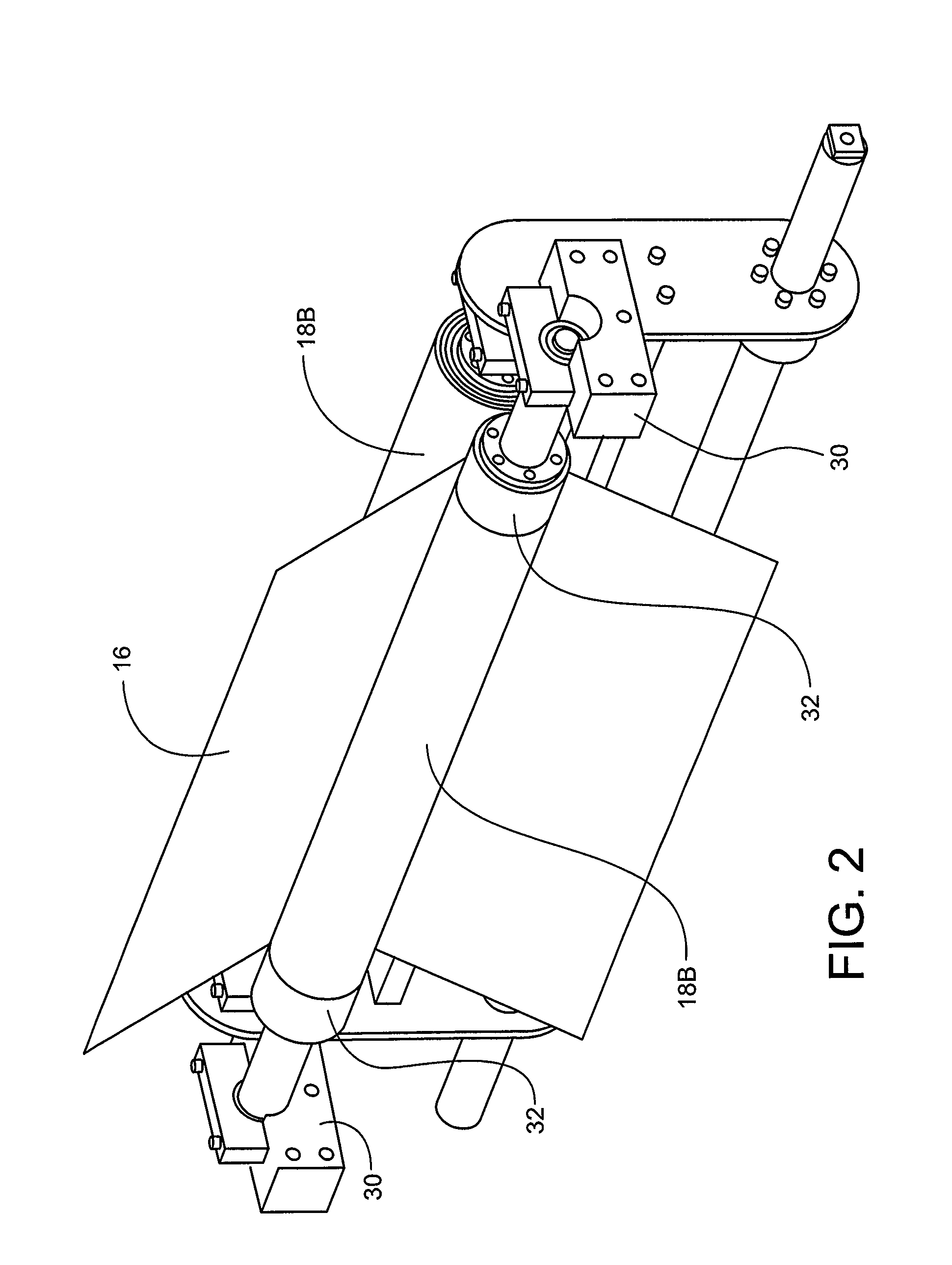
[0012]In accordance with at least selected embodiments, the instant invention relates to a new, improved or optimized continuous web inline testing apparatus, defect mapping system, and / or related methods. In accordance with at least certain embodiments, the instant invention relates to a continuous web inline testing apparatus adapted for use in a defect mapping system and to related methods of testing and mapping. More particularly, the instant invention relates to a new, improved or optimized continuous inline Hipot testing system. Even more specifically, the instant invention relates to inline Hipot testing on continuous non-conductive web material, which testing may detect defects and then map and record such defects automatically by a line scan camera system for quality grading purposes. In accordance with at l...


PUM


Abstract

In at least selected embodiments, an industrial size continuous Hipot testing system has defect mapping capability capable of finding pinholes, weak spots, and / or embedded conductive particles in non-conductive sheet materials. Continuous testing is made possible through a pair of uniquely designed rollers, such as conductive polymer rollers. Automatic defect mapping is also incorporated into the system through the integration of the Hipot testing and line scan camera systems. The unit potentially has wide applications in many industries, such as, for example, semi-conductors and electronics, medical, high end packaging, and so forth.

Description

CROSS-REFERENCE TO RELATED APPLICATION[0001]The instant application claims the benefit of and priority to U.S. Provisional Patent Application Ser. No. 61 / 895,572, filed Oct. 25, 2013.FIELD OF THE INVENTION[0002]In accordance with at least selected embodiments, the instant invention relates to a new, improved or optimized continuous web inline testing apparatus, defect mapping system, and / or related methods. In accordance with at least certain embodiments, the instant invention relates to a continuous web inline testing apparatus adapted for use in a defect mapping system and to related methods of testing and mapping. More particularly, the instant invention relates to a new, improved or optimized continuous inline Hipot testing system. Even more specifically, the instant invention relates to inline Hipot testing on continuous non-conductive web material, which testing may detect defects and then map and record such defects automatically by a line scan camera system for quality gradi...

Claims


Application Information

Patent Timeline
IPC IPC(8): G01R31/12
CPCG01R31/1218G01R31/1227G01N21/894G01N21/8901G01N21/8914G01N27/61
Inventor ADAMS, CHANGQING WANGLANDES, C. SHANEROBERTSON, DOUGLAS GEORGEFEREBEE, MARK W.
Owner CELGARD LLC
Learn More