Passive Q-switch modulated fiber laser

Inactive Publication Date: 2006-01-12
PHARMALASE
View PDF8 Cites 76 Cited by
  • Summary
  • Abstract
  • Description
  • Claims
  • Application Information

AI Technical Summary

Benefits of technology

[0017] What is needed is an inexpensive all-fiber laser emitting high average and peak power pulses. Suc

Problems solved by technology

The result in general is very short, intense burst of laser output that dumps all the accumulated population inversion in a single short laser pulse, typically only a few tens of nanoseconds long.
It has been shown that a passive Q switched yt

Method used


Image

  • Passive Q-switch modulated fiber laser
  • Passive Q-switch modulated fiber laser
  • Passive Q-switch modulated fiber laser

Examples


first preferred embodiment

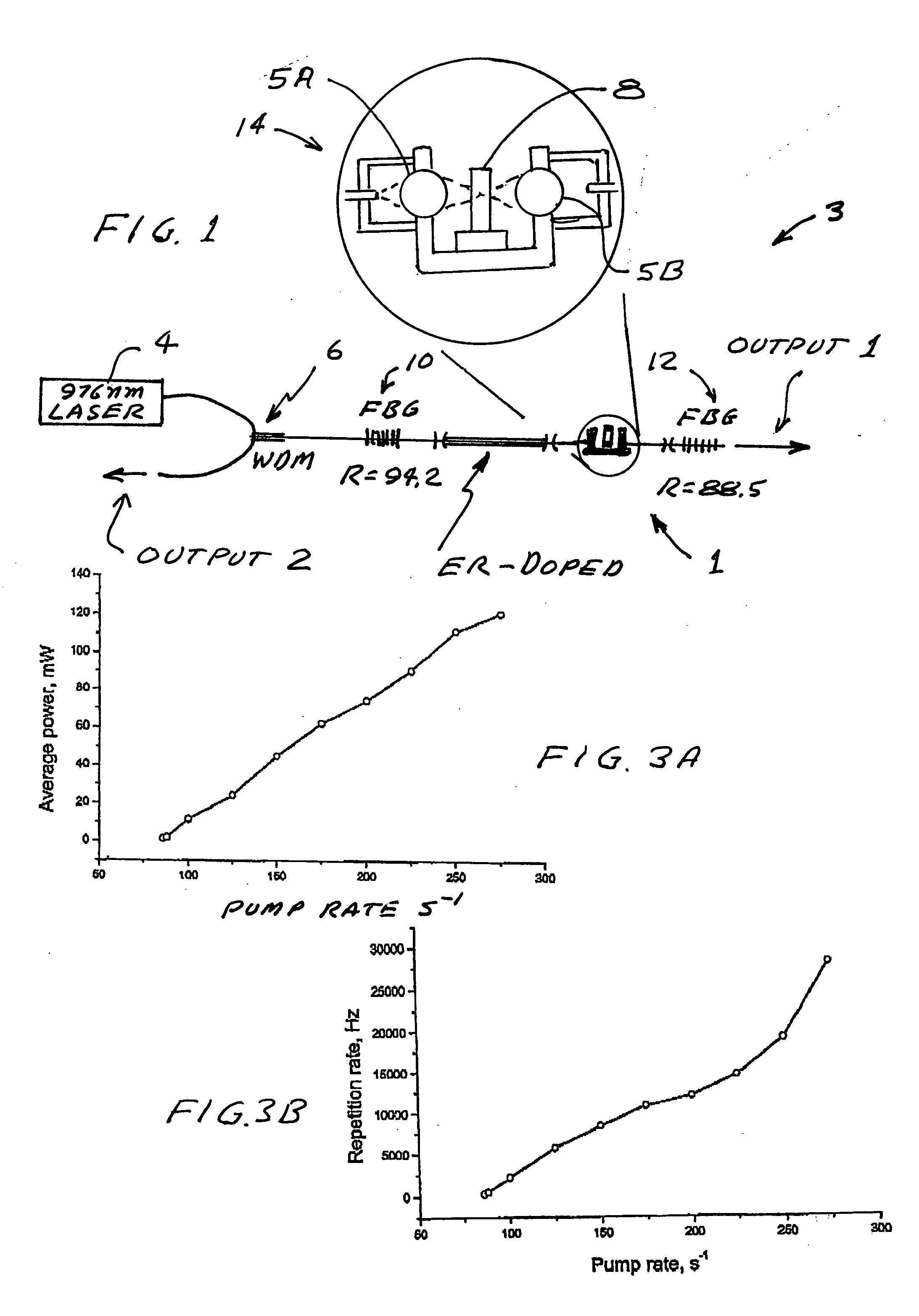
[0039]FIG. 1 is an optical schematic of a preferred embodiment 3 of the present invention. A laser cavity 1 is created with single mode erbium doped optical fiber 2 with a core diameter of 6.0 μm and a fiber length of anywhere between 0.2 m and 20 m. Applicant's preferred length is about 1 meter. The doping concentration of erbium ions is sufficient to produce about 1 dB / m to 350 dB / m absorption of the pump wavelength. Radiation from a pump diode laser 4 at a wavelength of 976 nm is launched with a wave divider multiplexer (WDM) coupler 6 into the master cavity. A Co2+:ZnSe crystal 8 with initial transmittance Tin=70-98% and a thickness 0.3 mm-1 mm is positioned within the cavity and the cavity is defined by two fiber Bragg grating mirrors 10 and 12 with maximum reflection of 94.2% (100-95%) and 88.5% (70-98%), respectively, both gratings are designed for a wavelength of 1560 nm. The laser includes a U-bench unit 14 with a Co2+:ZnSe crystal inside as shown in FIG. 1.

[0040] U-bench ...

second preferred embodiment

[0054] In this embodiment Cr2+:ZnSe is substituted for Co2+:Zn. The parameters of the U-bench were chosen to produce power density of the intra-cavity radiation in the center of U-bench at about 60 kW / cm2. The crystal Cr2+:ZnSe was placed near the center of U-bench to provide location of the beam waist of 1 μm close to the crystal center. The Cr2+:ZnSe crystal had antireflection coating at wavelength 1400-1800 nm. A sample of Cr2+:ZnSe crystal with initial transmittance Tin=50-98% and thickness 0.3-1 mm, and the two fiber Bragg grating (FBG) mirrors with maximum of reflection of 100-95% and 70-98%, respectively. The bleaching power of a Cr2+:ZnSe is 60 kW / cm2. Using this passive Q-switch modulator pulse duration as short as 10 ns to 500 ns might be obtained depending on the pump rate and the length of the fiber laser.

third preferred embodiment

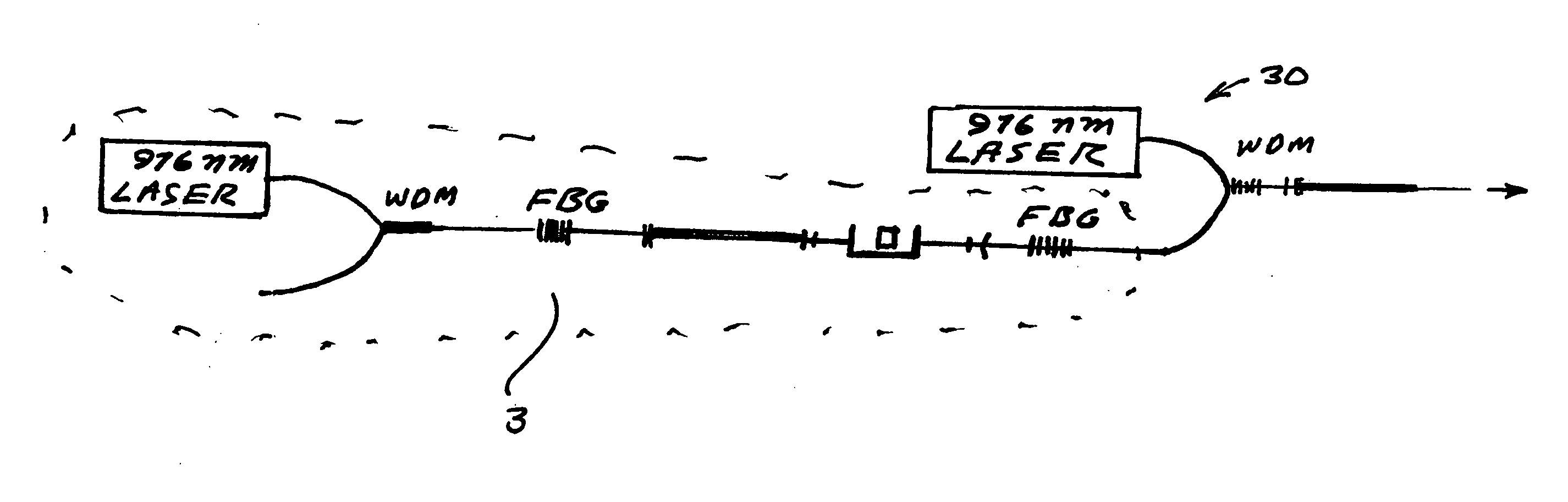
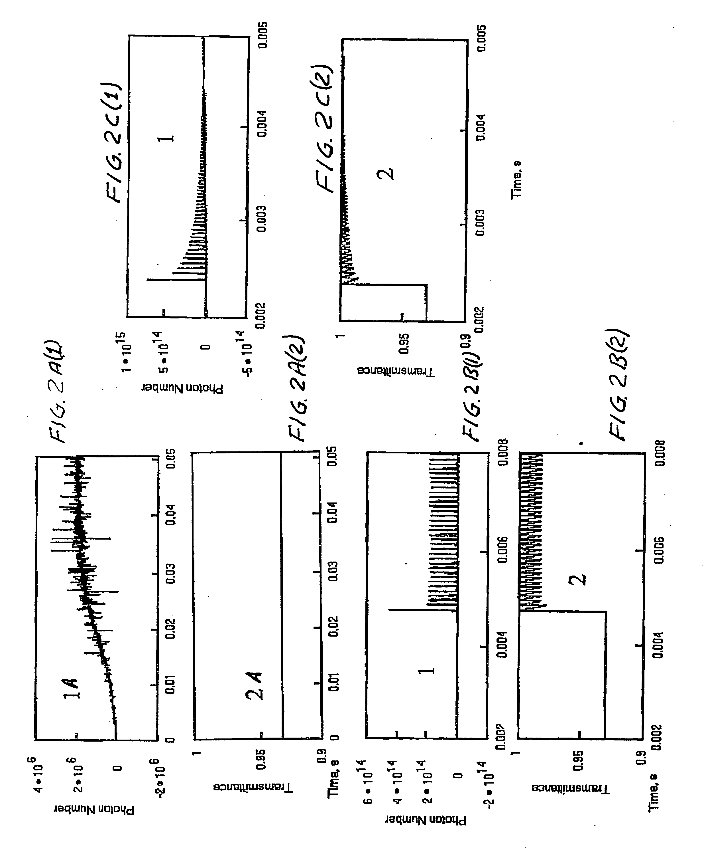
[0055] A third preferred embodiment relates to an all-fiber laser master oscillator and a power amplifier to form MOPA configuration and produce more powerful laser pulses. As described above in the fiber laser with passive Q-switch, it is not possible to get more power of certain type of laser pulses simply by increasing the pump level of the laser. This is because the mode changes from that shown in FIGS. 2B(1) and (2) to 2C(1) and (2). However, by using a secondary fiber power amplifier, it is possible to substantially increase the power of the laser pulses formed in the laser MOPA system. The optical setup is shown at FIG. 11. The portion 3 of FIG. 11 enclosed by dots is the same as the fiber laser 3 shown in FIG. 1. The fiber power amplifier 30 is connected at the output of the fiber laser. The pump set up of the power amplifier is similar to that of the master oscillator using wavelength division multiplexer (WDM) 6 as shown in FIG. 1. By using the MOPA configuration it is pos...


PUM


Abstract

An all-fiber erbium laser oscillating in a passive Q switched mode. The laser includes a crystal saturable absorber that may be Co2+:ZnSe or Cr2+:ZnSe. In preferred embodiments continuous pumping or short pulse pumping may be utilized. The laser is characterized by low threshold high-power, short-pulse generation. In preferred embodiments the threshold is only about 20 mW. The crystals are bleached at extremely low intensity, of about 0.8 kW/cm2 and provide moderate relaxation time of the excited state (290 μs) within a spectral range of about 1400-1800 nm. The simplicity of the design and low cost of that laser 2000).

Description

[0001] This invention relates to fiber lasers and in particular to passive Q-switch fiber lasers for medical applications. BACKGROUND OF THE INVENTION [0002] Q-switched lasers are well known. In these lasers the laser pumping process is allowed to build up to a much larger than usual population inversion inside the laser cavity while the cavity itself is kept from oscillating by removing the cavity feedback or greatly increasing the cavity losses—usually by blocking or removing one of the end mirrors. Then, after a large inversion has developed, the cavity feedback is restored; i.e., the “cavity Q” is switched back to its usual large value using some suitably rapid modulation method. The result in general is very short, intense burst of laser output that dumps all the accumulated population inversion in a single short laser pulse, typically only a few tens of nanoseconds long. The modulation method may be active and passive. Active modulation Q-switching in fiber lasers is currently...

Claims


Application Information

Patent Timeline
IPC IPC(8): H01S3/11H01S3/30
CPCA61B18/20H01S3/113H01S3/0675
Inventor TANKOVICH, NIKOLAILUKASHEV, ALEXEIKIRHANOV, ALEXANDERFILIPPOV, VALERYSTAROOVMOV, ANDREI
Owner PHARMALASE
Why Eureka
Try Eureka