Method for cleaning surface of irregular columnar object
It is an object surface and irregular technology, which is applied in cleaning methods and utensils, cleaning methods using tools, chemical instruments and methods, etc. It can solve problems such as low efficiency and insufficient cleaning, and achieve the goal of improving cleaning efficiency and cleaning effect Effect
- Summary
- Abstract
- Description
- Claims
- Application Information
AI Technical Summary
Problems solved by technology
Method used
Image
Examples
Embodiment 1
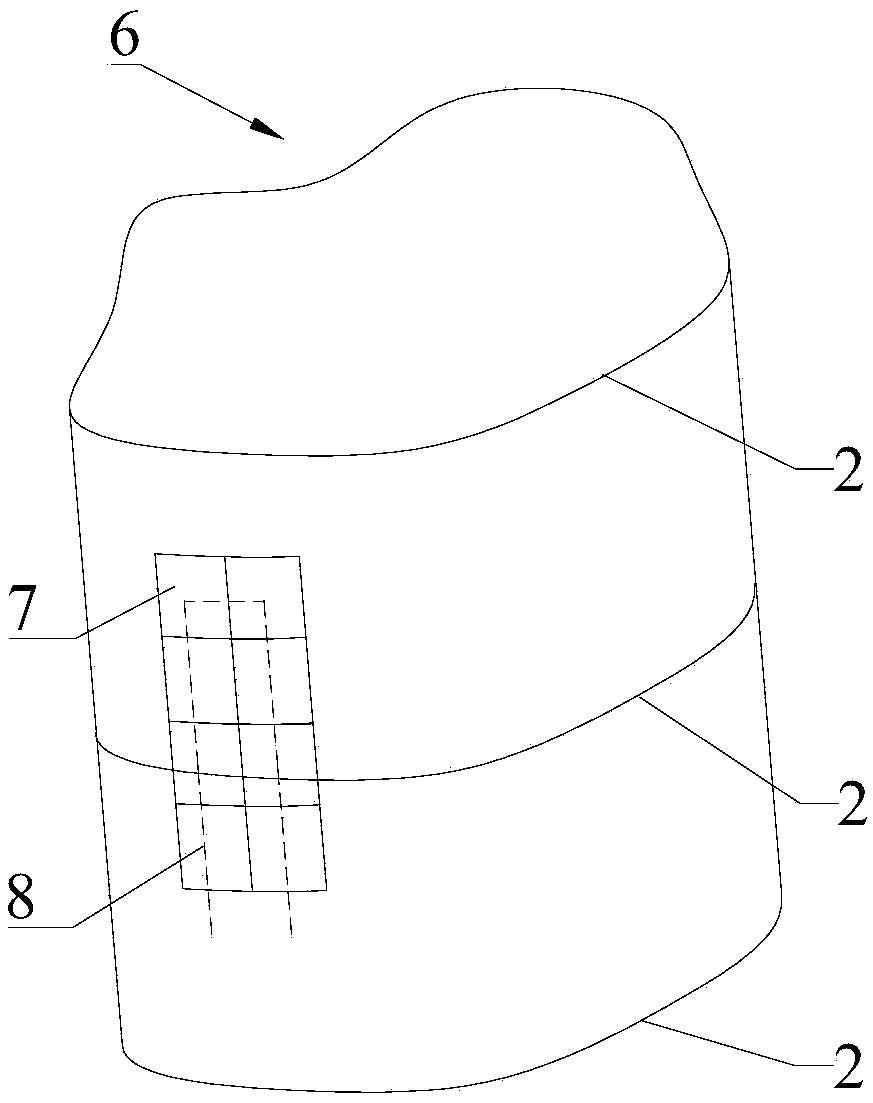
[0056] Please refer to Figure 1 to Figure 5 , Embodiment 1 of the present invention is: a method for cleaning the surface of an irregular columnar object, comprising the following steps:
[0057] S1: building a three-dimensional model of the irregular columnar object 6;
[0058] S2: Taking the area of the cleaning unit as the basic unit 7, arrange and cover the surface of the three-dimensional model;
[0059] S3: connect the central points of all the basic units 7 in series to obtain the cleaning trajectory 8;
[0060] S4: Clean the irregular columnar object 6 according to the cleaning track line 8 .
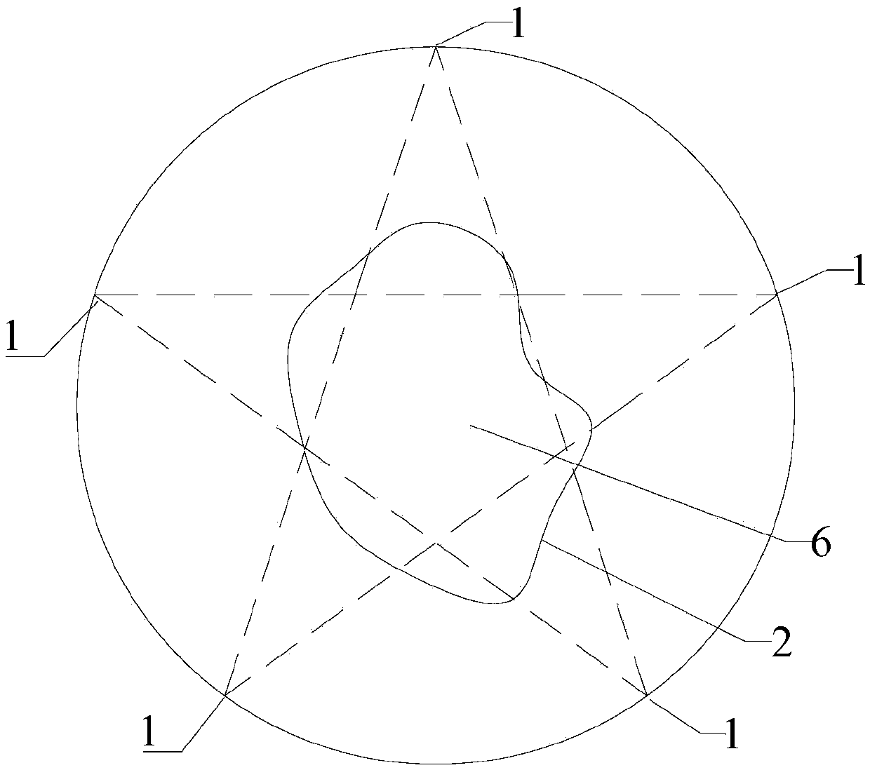
[0061] Further, the establishment of the three-dimensional model of the irregular columnar object 6 in step S1 specifically includes the following steps:
[0062] S11: Arranging several preset light sources 1 evenly in a ring shape, and setting the irregular columnar object 6 in the middle of the ring surrounded by the several preset light sources 1;
[0063] S12: Perform t...
Embodiment 2
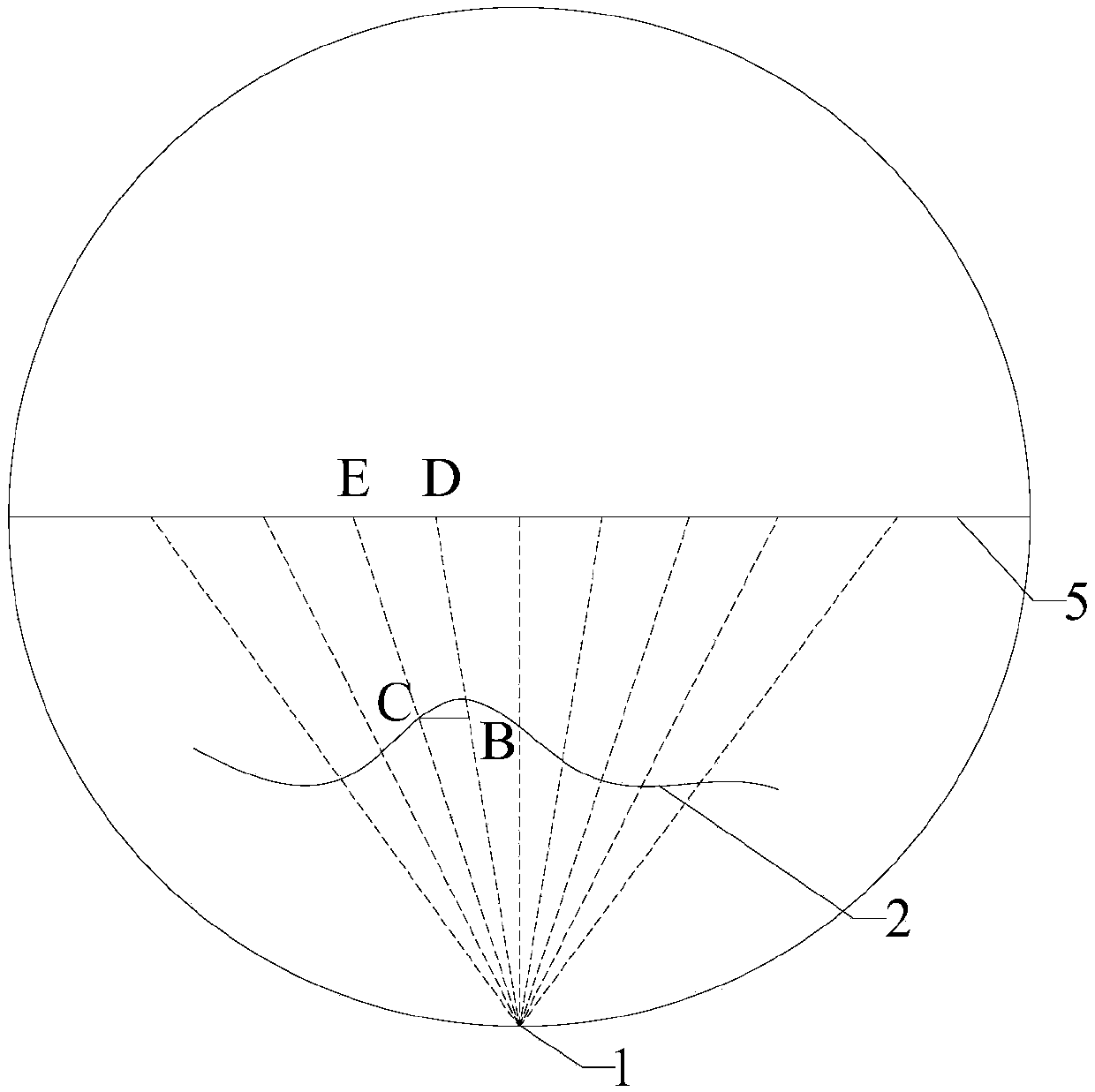
[0080] Please combine figure 1 , figure 2 and Figure 4 to Figure 6 , Embodiment 2 of the present invention proposes another scheme on the basis of Embodiment 1. The difference from Embodiment 1 is that the contour line 2 of the irregular columnar object 6 is not obtained by connecting the adjacent measured contour line segments end-to-end. , but obtained by calculating the coordinates of the endpoints on the same side of the measured contour line segment and then connecting the coordinates of the endpoints in sequence. Specifically: generating the standard reference electronic signal 3 in S12 specifically includes: establishing a two-dimensional coordinate system to obtain the intersection points ( Figure 6 point D and point E), detect the line segment corresponding to the divergent light of the fan on the X axis, and obtain the standard reference electronic signal 3.
[0081] After step S121, a further step is included: divide the obtained standard reference electronic ...
PUM
 Abstract
Description
Claims
Application Information
 - R&D
- Intellectual Property
- Life Sciences
- Materials
- Tech Scout
- Unparalleled Data Quality
- Higher Quality Content
- 60% Fewer Hallucinations
Browse by: Latest US Patents, China's latest patents, Technical Efficacy Thesaurus, Application Domain, Technology Topic, Popular Technical Reports.
© 2025 PatSnap. All rights reserved.Legal|Privacy policy|Modern Slavery Act Transparency Statement|Sitemap|About US| Contact US: help@patsnap.com


