Centering compressing device and method for flue flange

A technology of pressing device and flange, applied in workpiece clamping devices, hand-held tools, manufacturing tools, etc., can solve problems such as low construction efficiency, easy injury to operators, safety accidents, etc., to improve installation work efficiency, enhance The effect of construction safety and simple operation

Active Publication Date: 2018-04-13
CHINA FIRST METALLURGICAL GROUP
View PDF8 Cites 1 Cited by
  • Summary
  • Abstract
  • Description
  • Claims
  • Application Information

AI Technical Summary

Problems solved by technology

This method has low construction efficiency, is easy to injure workers, leads to safety accidents, and easily causes deformation of the flange, which affects the sealing effect of the flange.

Method used


Image

  • Centering compressing device and method for flue flange

Examples


Embodiment Construction

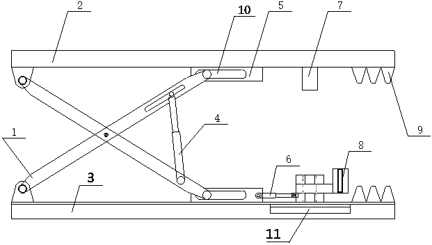
[0019] In order to better understand the present invention, below in conjunction with embodiment and accompanying drawing, technical scheme of the present invention is described further (as figure 1 shown).

[0020] A flue flange centering and pressing device, which includes an upper splint 2 and a lower splint 3, the upper splint 2 and the lower splint 3 are arranged symmetrically in parallel up and down, and the upper splint 2 and the lower splint 3 are connected by a lifting device, The lifting device (composed of movable frame 1, clamping hydraulic cylinder 4, connecting plate 5 and bar-shaped connecting hole 10) is located at the second half of the splint (the splint is the general name of the upper splint 2 and the lower splint 3); The inner sides of the splint 2 and the lower splint 3 are provided with toothed plates 9, and the two toothed plates 9 are distributed parallel and symmetrical up and down, and are respectively located at the front ends of the upper splint 2 ...


PUM


Abstract

The invention relates to a centering compressing device for a flue flange. The centering compressing device for the flue flange comprises an upper clamping plate and a lower clamping plate; the upperclamping plate is connected with the lower clamping plate through a lifting device; a toothed plate is arranged on the inner side of each of the upper clamping plate and the lower clamping plate; thetwo toothed plates are symmetrically distributed in parallel up and down; a fixed pin is also arranged on the inner side of the upper clamping plate and is positioned between the lifting device and the corresponding toothed plate; a movable pin is mounted on the inner side of the lower clamping plate; the movable pin is also positioned between the lifting device and the corresponding toothed plate; the movable pin is mounted on the lower clamping plate through a sliding block and a sliding rail; a moving hydraulic cylinder which is used for driving the movable pin to move forward and backwardis also arranged on the movable pin; the two ends of the moving hydraulic cylinder are respectively hinged to the movable pin and the lower clamping plate; and when the movable pin is positioned in the middle of the sliding rail, the fixed pin is positioned right above the movable pin. According to the centering compressing device for the flue flange, the flue flange is centred and compressed quickly; the centering compressing device for the flue flange is light, convenient and small, and is easy to operate; the construction safety can be greatly improved; the mounting work efficiency is improved; and convenience is provided for mounting of flue replacement.

Description

technical field [0001] The invention relates to the field of converter vaporization flue construction, in particular to a flue flange centering and pressing device and method. Background technique [0002] Converter vaporization flue is one of the main supporting equipment for converter steelmaking. This equipment must collect high-temperature flue gas to the maximum extent during operation, and withstand high furnace gas temperature and severe and frequent temperature changes. The working conditions are extremely harsh and it is easy to stick Due to the spattered steel slag, the update frequency is very high, but it is very inconvenient to disassemble. The converter flue is bulky and heavy, and the flue is mainly connected by flanges. During the installation process, the centering of the flue is a big problem. The traditional centering method is to use a crowbar to pry the bolt holes to force the centering of the bolts, and then forcefully tighten the bolts to place the fl...

Claims


Application Information

Patent Timeline
Patent Type & Authority Applications(China)
IPC IPC(8): B25B11/02B25B27/14
CPCB25B11/02B25B27/14
Inventor 金钊陈海生马秉俊周汉生
Owner CHINA FIRST METALLURGICAL GROUP
Why Eureka
Try Eureka