Printing mechanism of ceramic decorating machine

A printing mechanism and printing machine technology, applied in printing machines, rotary printing machines, printing and other directions, can solve the problems of noise, scraper offset, affecting printing accuracy, etc., and achieve the effect of reducing noise, reducing vibration, and improving printing accuracy

Inactive Publication Date: 2018-04-13
佛山市嘉印机械设备有限公司
View PDF4 Cites 1 Cited by
  • Summary
  • Abstract
  • Description
  • Claims
  • Application Information

AI Technical Summary

Problems solved by technology

[0002] With the improvement of technology and people's living standards, the development of the ceramic machinery industry is also advancing by leaps and bounds. The ceramic printing machine is an important part of the ceramic industry; when the printing mechanism of the existing ceramic printing machine is working, the stepping motor is prone to produce a large Vibration, resulting in noise, reduces the comfort of the production environment; in addition, the printing mechanism of the existing ceramic printing machine, the position of the scraper is fixed and cannot be adjusted, and it is easy to shift after a long time of use, thereby affecting the printing accuracy; In addition, The squeegee tends to shift longitudinally when it is working, which affects the printing accuracy

Method used


Image

  • Printing mechanism of ceramic decorating machine
  • Printing mechanism of ceramic decorating machine
  • Printing mechanism of ceramic decorating machine

Examples


Embodiment Construction

[0019] The present invention will be described in further detail below in conjunction with accompanying drawing, and these accompanying drawings are all simplified schematic diagrams, only illustrate the basic structure of the present invention in a schematic way, and the direction of this specific implementation is based on figure 1 Orientation is standard.

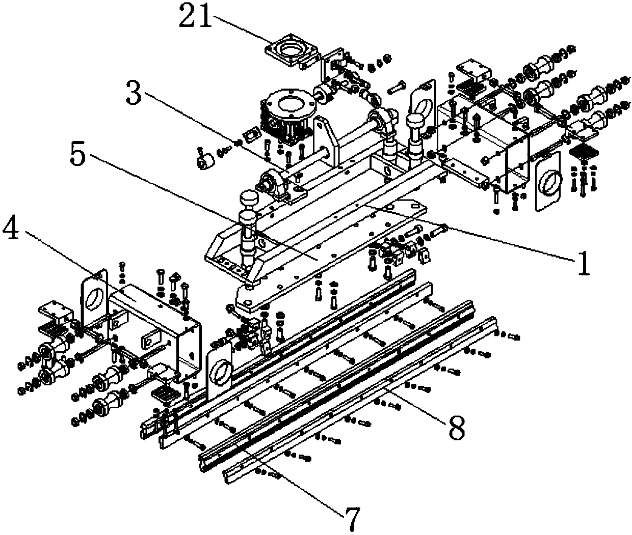
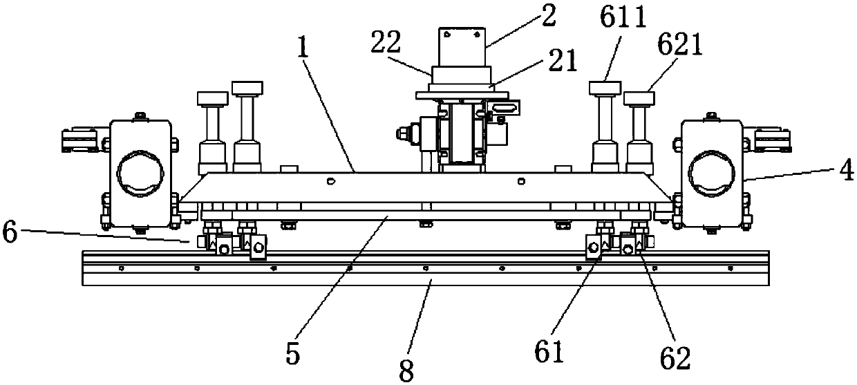
[0020] Such as Figure 1-Figure 5 As shown, the printing mechanism of the ceramic printing machine of the present invention includes a beam frame 1, a stepping motor 2, a rotating shaft 3, a roller box 4, a scraper mounting plate 5, a scraper 6, a knife hanging plate 7 and a knife clamping plate 8, wherein:

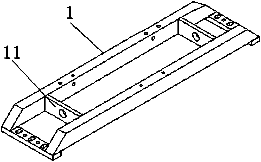
[0021] The crossbeam frame 1 is arranged in a rectangular frame structure, and the left and right parts of the crossbeam frame 1 are provided with reinforcing plates 11. By providing the reinforcing plates 11, the structural strength of the crossbeam frame 1 is improved, and its use stability is improved.

[0022] ...


PUM


Abstract

The invention discloses a printing mechanism of a ceramic decorating machine. The printing mechanism is small in noise and high in printing accuracy, and comprises a transverse beam support, a stepping motor, a rotating haft, a scraper installing plate, scrapers, a scraper hanging plate and a scraper clamping plate, the stepping motor and the rotating shaft are arranged above the transverse beam support and are in transmission connection through a stepping motor transition flange, a damping mat is arranged between the stepping motor and the stepping motor transition flange, the two scrapers are arranged on the two sides of the bottom of the scraper installing plate, the scrapers comprise the front scraper and the back scraper, a first adjusting screw is arranged at the top of the front scraper, a second adjusting screw is arranged at the top of the back scraper, the scraper hanging plate and the scraper clamping plate are arranged below the scrapers and are parallel, a gap is reservedbetween the scraper hanging plate and the scraper clamping plate, the scrapers are located in the gap between the scraper hanging plate and the scraper clamping plate, the scraper clamping plate is provided with a clamping plate at the position located on the side face of the gap, and a plurality of compressed springs are arranged between the clamping plate and the scraper clamping plate.

Description

technical field [0001] The invention relates to a printing mechanism of a ceramic printing machine. Background technique [0002] With the improvement of technology and people's living standards, the development of the ceramic machinery industry is also advancing by leaps and bounds. The ceramic printing machine is an important part of the ceramic industry; when the printing mechanism of the existing ceramic printing machine is working, the stepping motor is prone to produce a large Vibration, resulting in noise, reduces the comfort of the production environment; in addition, the printing mechanism of the existing ceramic printing machine, the position of the scraper is fixed and cannot be adjusted, and it is easy to shift after a long time of use, thereby affecting the printing accuracy; In addition, The squeegee tends to shift longitudinally when it is working, which affects the printing accuracy. [0003] Therefore, there is a special need for a printing mechanism of a c...

Claims


Application Information

Patent Timeline
Patent Type & Authority Applications(China)
IPC IPC(8): B41F17/00
CPCB41F17/00
Inventor 邹梓常
Owner 佛山市嘉印机械设备有限公司
Why Eureka
Try Eureka